Wireless power multi-charging method and power transmitter

a multi-charging and wireless technology, applied in the directions of transportation and packaging, arrangements for several simultaneous batteries, and ac network voltage adjustment, etc., can solve the problem that the power transmitter cannot charge the second power receiver

Active Publication Date: 2013-04-04
SAMSUNG ELECTRONICS CO LTD
View PDF5 Cites 292 Cited by
  • Summary
  • Abstract
  • Description
  • Claims
  • Application Information

AI Technical Summary

Benefits of technology

[0007]Accordingly, an aspect of the present invention is to solve at least the above-described problems occurring in the prior art, and to provide at least the advantages described below.

Problems solved by technology

Consequently, the power transmitter fails to charge the second power receiver.

Method used


Image

  • Wireless power multi-charging method and power transmitter
  • Wireless power multi-charging method and power transmitter
  • Wireless power multi-charging method and power transmitter

Examples


Embodiment Construction

[0017]Hereinafter, various embodiments of the present invention will be described with reference to the accompanying drawings. In the following description, like elements will be designated by like reference numerals throughout the drawings. Further, definitions in the following description are provided only to aid in the general understanding of the present invention. Further, in the following description of the present invention, a detailed description of known functions and configurations is omitted to avoid obscuring the subject matter of the present invention.

[0018]Hereinafter, in the embodiments of the present invention, an ordinal number, such as first, second, or the like may be used. Such terminology is not used to indicate importance, order or sequence of a corresponding component but merely used to distinguish the corresponding component or step from other components or steps.

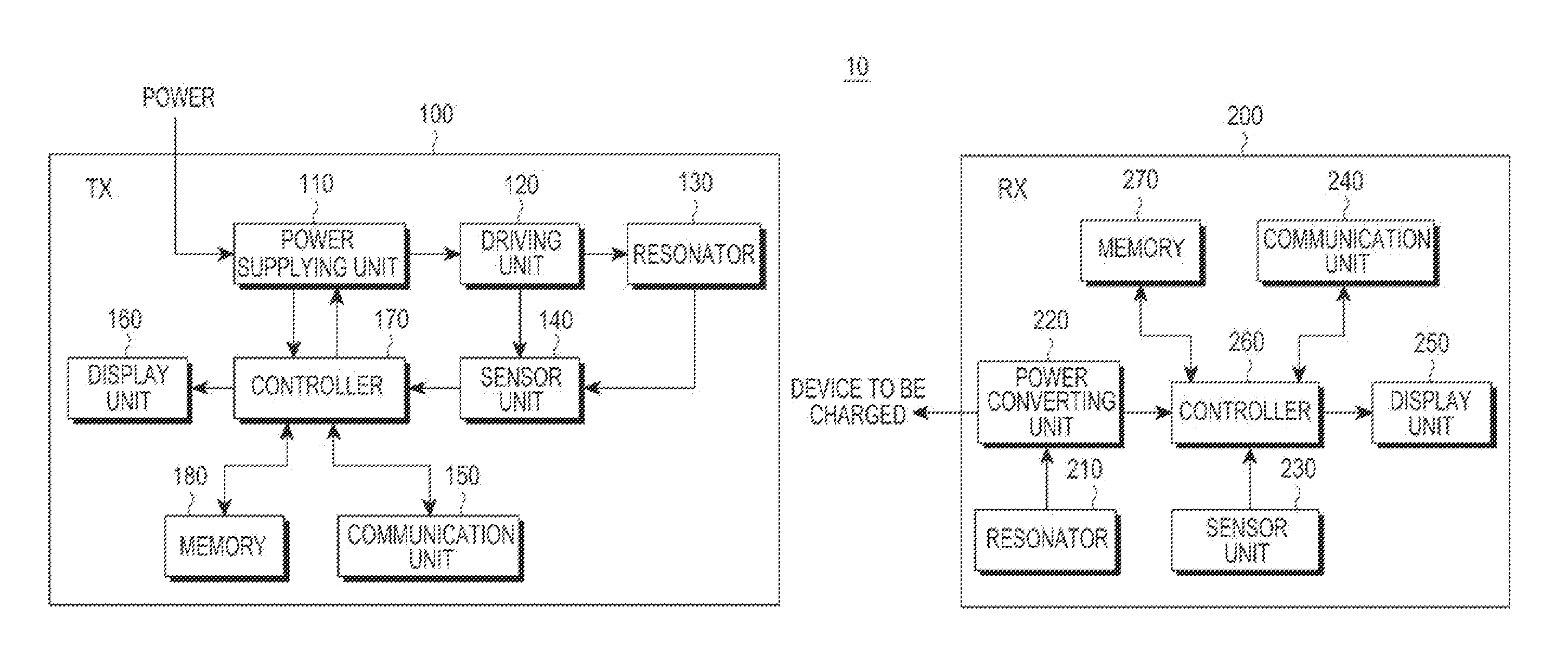
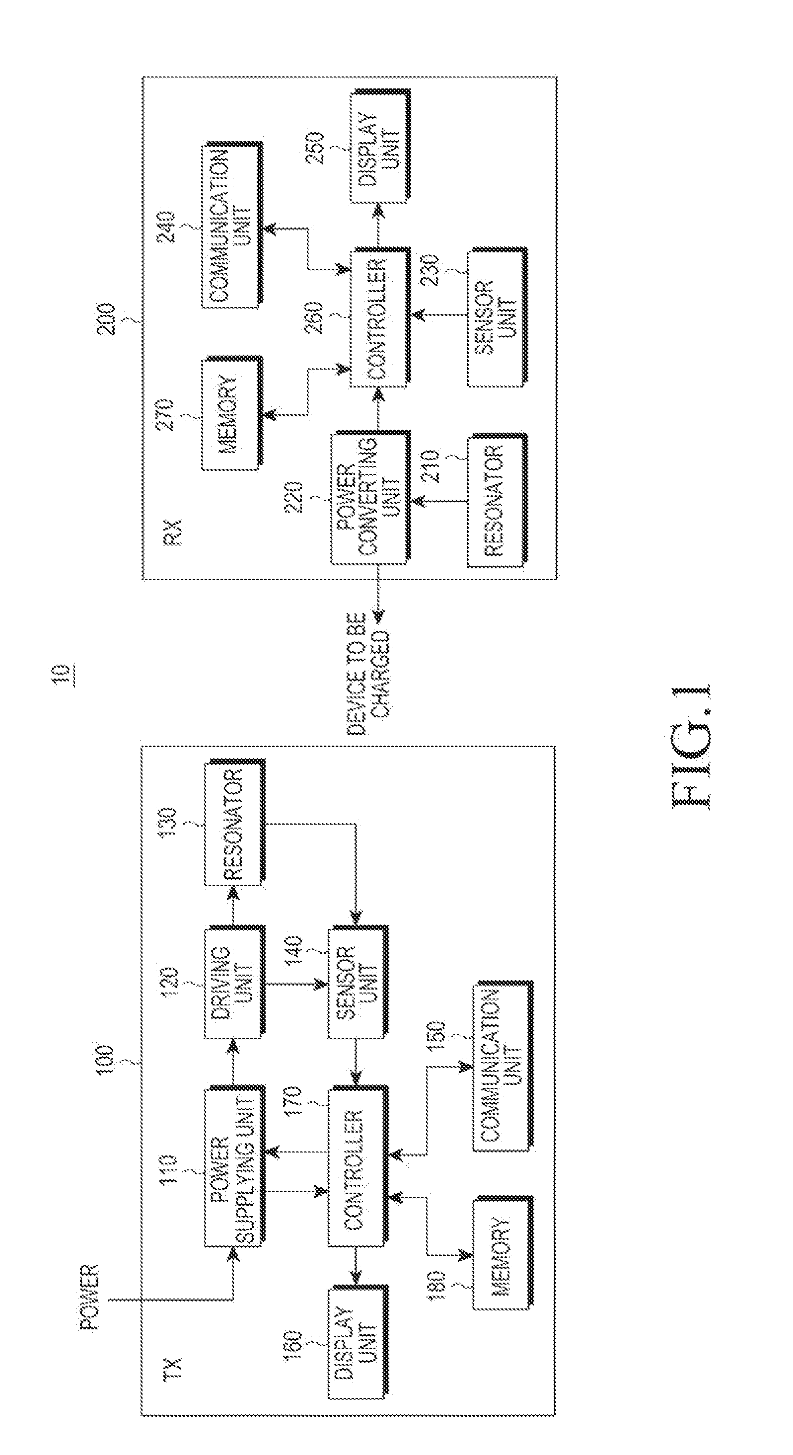
[0019]FIG. 1 is a diagram illustrating a wireless multi-charge system according to an embodiment ...


PUM


Abstract

A wireless multi-charging method of a power transmitter that wirelessly transmits power includes sensing a first power receiver, increasing a transmission power required for charging the first power receiver, sensing a second power receiver, decreasing the transmission power required for suspending charging of the first power receiver, and increasing the transmission power required for simultaneously charging both the first power receiver and the second power receiver.

Description

PRIORITY[0001]This application claims priority under 35 U.S.C. §119(a) to Korean Application Serial No. 10-2011-0100681, which was filed in the Korean Intellectual Property Office on Oct. 4, 2011, the entire content of which is incorporated herein by reference.BACKGROUND OF THE INVENTION[0002]1. Field of the Invention[0003]The present invention relates generally to a wireless charging method, and more particularly, to a method and a power transmitter for wireless multi-charging.[0004]2. Description of the Related Art[0005]A conventional resonant type wireless charge system includes a power transmitter equipped with a first resonator and a power receiver equipped with a second resonator. When the second resonator is located in a Radio Frequency (RF) field generated by the first resonator. The second resonator absorbs the RF field and power transmission occurs.[0006]When the second power receiver enters into a charging area of the power transmitter (that is, an effective RF field area...

Claims


Application Information

Patent Timeline
Patent Type & Authority Applications(United States)
IPC IPC(8): H02J17/00H02J7/00
CPCH02J7/0027H02J17/00H02J7/025H02J50/40H02J50/12H02J50/20H04B5/0037H02J7/0044H02J50/80H02J50/90
Inventor LEE, KYUNG-WOOKIM, JOON-ILBYUN, KANG-HO
Owner SAMSUNG ELECTRONICS CO LTD
Why Eureka
Try Eureka