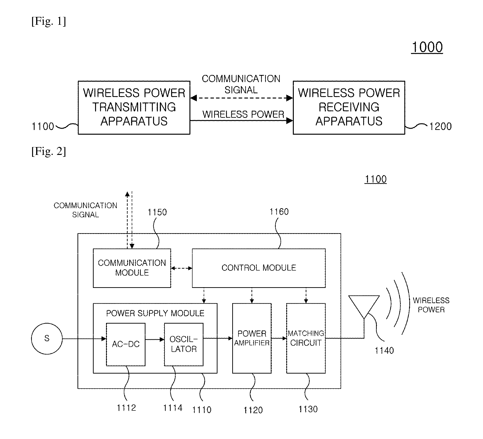
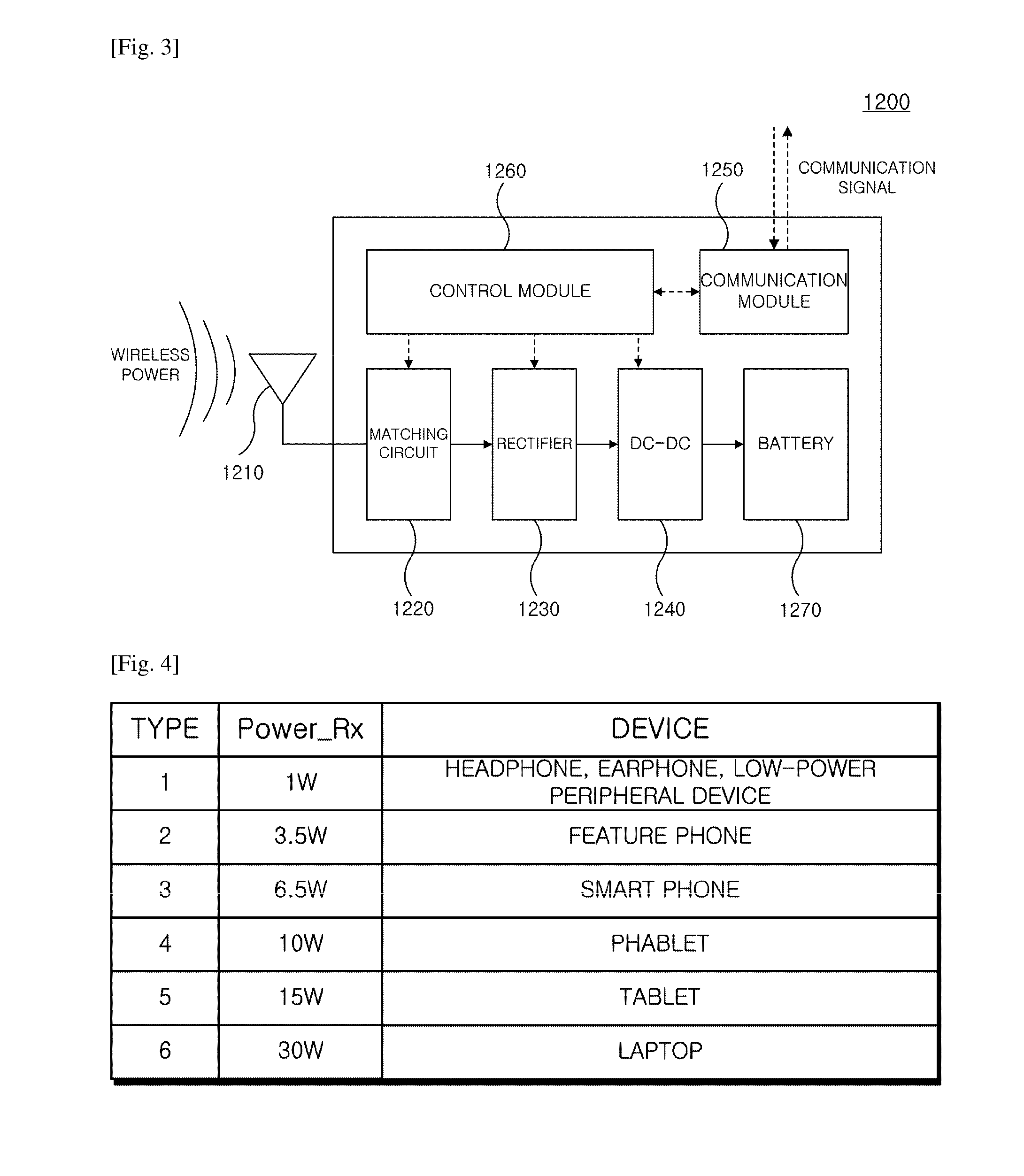
Wireless power transmission apparatus and wireless power transmission method

a wireless power transmission and wireless technology, applied in transmission, transportation and packaging, electric vehicles, etc., can solve the problem of remarkably low degree of positional freedom, and achieve the effect of efficiently sensed and minimal power consumption

Active Publication Date: 2016-11-17
WILUS INST OF STANDARDS & TECH
View PDF1 Cites 299 Cited by
  • Summary
  • Abstract
  • Description
  • Claims
  • Application Information

AI Technical Summary

Benefits of technology

The present invention provides a wireless power transmitting apparatus that can define multiple standby states and control the transmission of detector signals based on each standby state, thereby minimizing power consumption. The apparatus is also compatible with various types of wireless power receiving apparatuses and prevents situations such as power state oscillation and cross connection between devices during power transmission. Additionally, the apparatus can efficiently sense log objects and set charging priorities for each receiving apparatus, as well as verify charging states of multiple wireless power receiving apparatuses at once during power transmission.

Problems solved by technology

This patent discusses two main types of wireless power transmission technologies: the first uses electromagnetic waves while the second involves inducing currents through magnetic field interactions. Both have advantages and limitations, including range (the maximum distance over which they can transfer power) and sensitivity to alignment. However, the newest approach called resonant magnetic coupling allows for longer ranges and more efficient use of available space. Overall, this technology offers greater flexibility and ease of use when implementing wireless power solutions.

Method used


Image

  • Wireless power transmission apparatus and wireless power transmission method
  • Wireless power transmission apparatus and wireless power transmission method
  • Wireless power transmission apparatus and wireless power transmission method

Examples


Embodiment Construction

Technical Problem

[0008]The present invention has been made in an effort to reduce standby power consumption due to transmission of a weak detector signal and / or a strong detector signal in a standby state of a wireless power transmitting apparatus.

[0009]The present invention has also been made in an effort to provide a method for controlling various situations which can occur when the wireless power transmitting apparatus transmits power to a plurality of wireless power receiving apparatuses.

[0010]The present invention has also been made in an effort to provide a method in which the wireless power transmitting apparatus can efficiently control the plurality of wireless power receiving apparatuses.

Technical Solution

[0011]An exemplary embodiment of the present invention provides a wireless power transmitting method of a wireless power transmitting apparatus, wherein a standby state of determining whether at least one wireless power receiving apparatus is positioned within a wireless c...


PUM


Abstract

The present invention relates to a method for verifying a charging state of a wireless power receiving apparatus in the wireless power transmitting apparatus, and more particularly, to an apparatus and a method for efficiently performing and controlling wireless power transmission.
To this end, the present invention provides a wireless power transmitting method, wherein a standby state of determining whether at least one wireless power receiving apparatus is positioned within a wireless charge range of the wireless power transmitting apparatus and a power transfer state of transmitting power to the corresponding wireless power receiving apparatus when at least one wireless power receiving apparatus is detected in the standby state are provided, and the standby state includes a first standby state of periodically transmitting a weak detector signal and a strong detector signal and a second standby state in which at least one of a transmission period of the weak detector signal and a transmission period of the strong detector signal is different from that of the first standby state, the method including: determining any one state of the first standby state and the second standby state of the wireless power transmitting apparatus; and transmitting the weak detector signal and the strong detector signal based on the determined standby state, wherein the transmission period of the weak detector signal in the second standby state is longer than the transmission period of the weak detector signal in the first standby state.

Description


Claims


Application Information

Patent Timeline
Owner WILUS INST OF STANDARDS & TECH
Why Eureka
Try Eureka