Comissioning load control systems

a load control and load technology, applied in the direction of circuit arrangement, dc source parallel operation, instruments, etc., can solve the problems of time-consuming and inconvenient current association methods, and the difficulty of reconfiguring current associations

Active Publication Date: 2014-09-18
LUTRON TECH CO LLC
View PDF35 Cites 299 Cited by
  • Summary
  • Abstract
  • Description
  • Claims
  • Application Information

AI Technical Summary

Benefits of technology

[0011]Communications between the user device and the load control devices may be performed via a wireless communications module. The wireless communications module may be capable of communicating with the user device via a communications channel and with the load control devices via another communi

Problems solved by technology

Accordingly, current association methods may be time consuming and inconvenient.
Current associations may also be difficult to reconfigure once they have been established

Method used


Image

  • Comissioning load control systems
  • Comissioning load control systems
  • Comissioning load control systems

Examples


Embodiment Construction

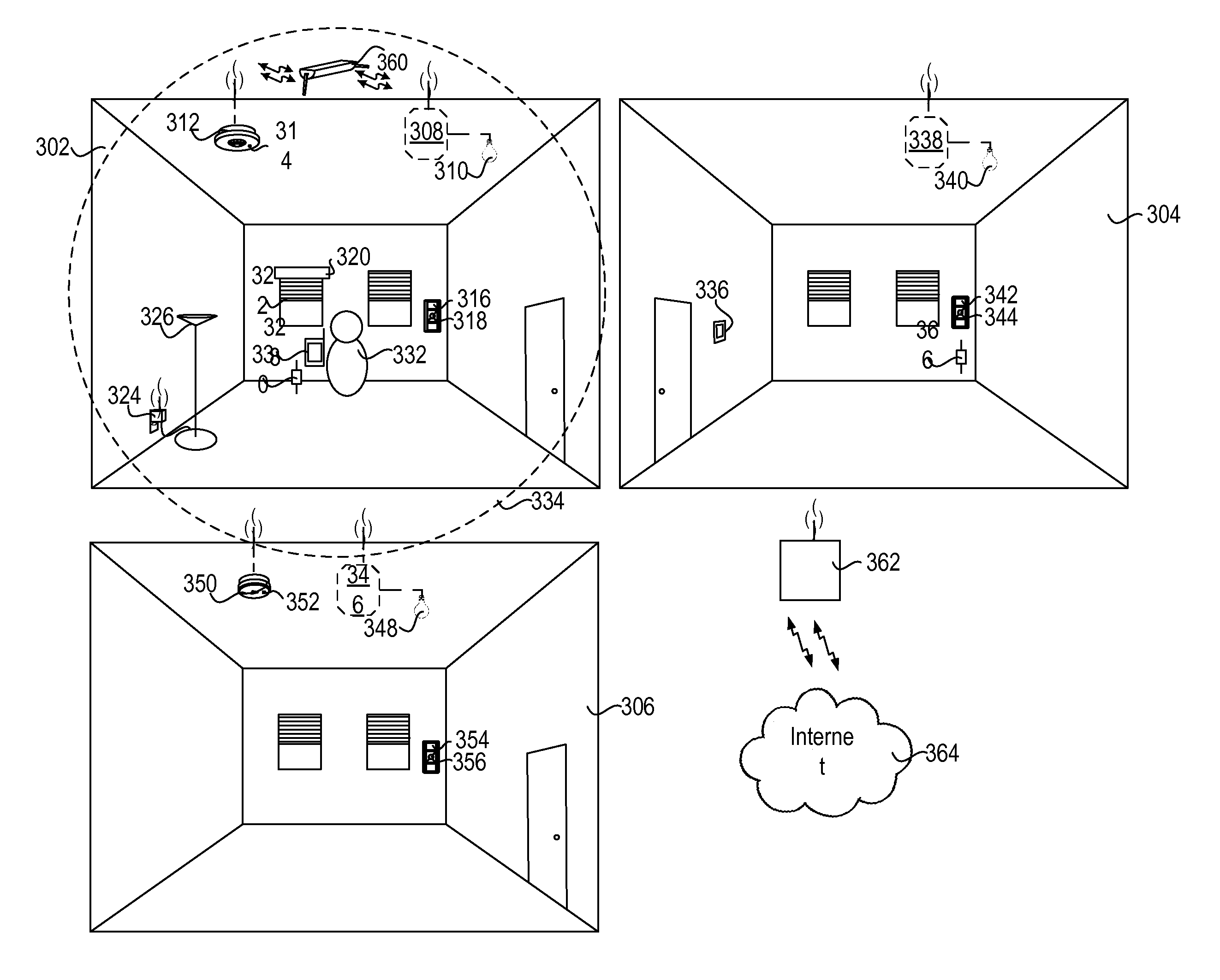
[0027]FIG. 3A depicts a representative environment for associating control devices, which may include control-source devices and control-target devices. When a control-target device is associated with a control-source device, the control target device may be responsive to the control-source device. A control device may be both a control-target and a control-source device. As shown in FIG. 3A, rooms 302, 304, and 306 may be installed with one or more control-target devices, e.g., load control devices for controlling the electrical loads within a room or building. Each load control device may be capable of directly controlling the amount of power provided to an electrical load and may be controlled by a control-source device. Example control-target devices may include lighting control devices 308, 338, and 346 (e.g., ballasts, LED drivers, or dimmer switches) for controlling the amount of power provided to lighting loads 310, 340, and 348, respectively, a motorized window treatment 32...


PUM


Abstract

A load control system may include load control devices for controlling power provided to an electrical load. The load control devices may include a control-source device and a control-target device. The control-target device may control the power provided to the electrical load based on digital messages received from the control-source device. A user device may discover load control devices when the load control devices are within an established range associated with the user device. The user device and the load control devices may communicate via a wireless communications module. The established range may be adjusted based on the configurable transmit power of the user device or the wireless communications module associated with the user device. A discovered control-target device may be associated with a control-source device to enable the control-target device to control the power provided to the electrical load based on digital messages received from the control-source device.

Description

BACKGROUND[0001]A user environment, such as a residence or an office building for example, may be configured using various types of load control systems. A lighting control system may be used to control the lighting loads in the user environment. A motorized window treatment control system may be used to control the natural light provided to the user environment. A heating, ventilation, and air-conditioning (HVAC) system may be used to control the temperature in the user environment. Each load control system may include various control devices, including control-source devices and control-target devices. The control-target devices may receive digital messages, which may include load control instructions, for controlling an electrical load from one or more of the control-source devices. The control-target devices may be capable of directly controlling an electrical load. The control-source devices may be capable of indirectly controlling the electrical load via the control-target dev...

Claims


Application Information

Patent Timeline
IPC IPC(8): H02J4/00
CPCH05B37/0272H02J4/00H05B47/19G08C17/02
Inventor CRAFTS, JORDANFRICKE, WILLIAM BRYCELUDWING, JR., STEPHEN M.LENZ, JONATHAN T.BARNES, BRYAN ROBERTBARCO, KYLE THOMAS
Owner LUTRON TECH CO LLC
Why Eureka
Try Eureka