
Exterior wiring harness

Inactive Publication Date: 2018-11-29
AUTONETWORKS TECH LTD +2
View PDF1 Cites 2 Cited by
  • Summary
  • Abstract
  • Description
  • Claims
  • Application Information

AI Technical Summary

Benefits of technology

The invention is a special wiring harness that contains a wire. A fabric made of fibrous resin is folded over the wire and attached to its inner surface. This fabric wraps tightly around the wire and absorbs its vibration, reducing the noise it makes. A shield layer is attached to the resin fabric to further shield the wire. The resin fabric is easy to bind and can be formed into a thicker material to better absorb sound. Overall, the invention effectively shields the wire and reduces noise.

Problems solved by technology

The hitting sound is uncomfortable to users.
H11-353952, a wiring harness becomes thicker, thereby causing a problem for wire routing in a narrow space.

Method used


Image

  • Exterior wiring harness
  • Exterior wiring harness
  • Exterior wiring harness

Examples


first embodiment

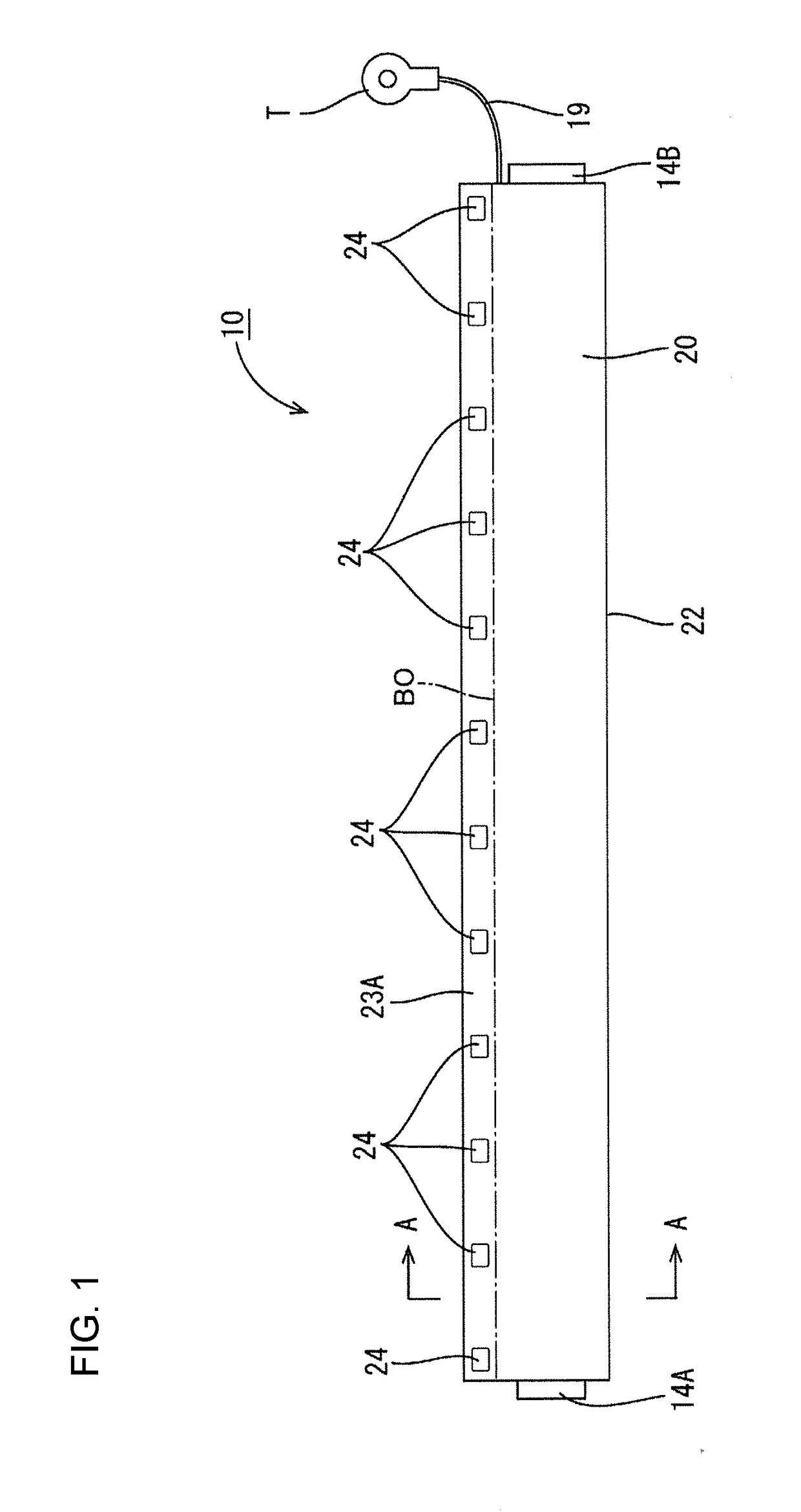
[0019]A first embodiment is described with reference to FIGS. 1 to 6.

[0020]An exterior wiring harness 10 of this embodiment can be used for example as a conductive path of a connection path between a battery pack (not shown) serving as a drive source of an electric or hybrid vehicle and a device (not shown) such as an inverter or motor. Note that the battery pack includes a battery module with a plurality of battery cells and an ECU (Electronic Control Unit) for managing and controlling voltages and the like of the battery cells.

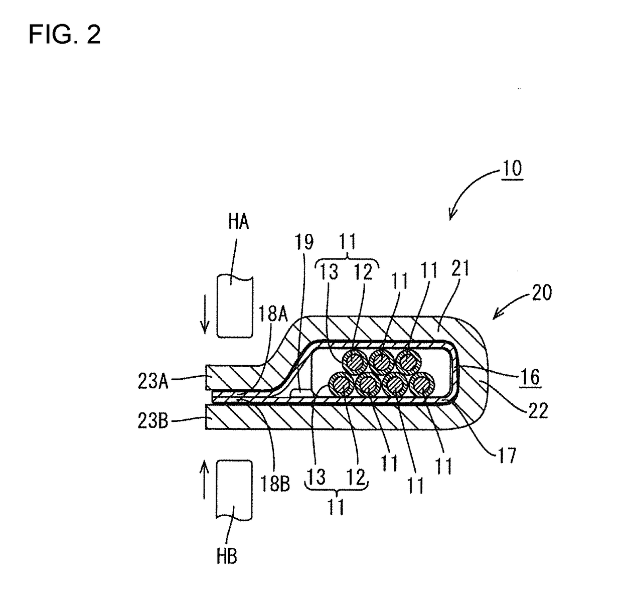
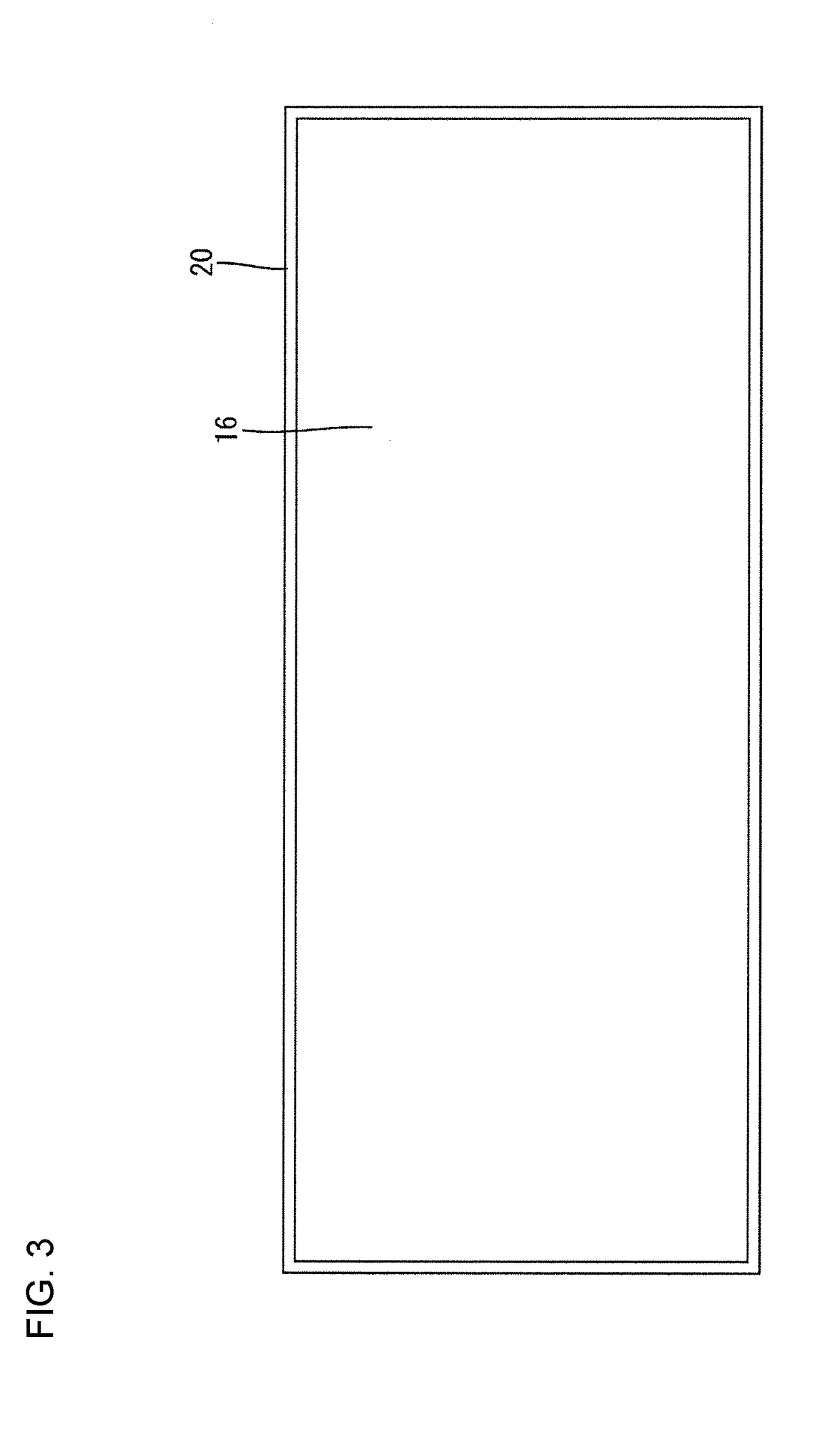
[0021]As shown in FIG. 2, the exterior wiring harness 10 includes wires 11 (seven in this embodiment), a resin fabric 20 for collectively enclosing the wires 11 and a shield layer 16 attached to an inner surface of the resin fabric 20. Each wire 11 is a coated wire having a circular cross-section and including a core 12 and an insulation coating 13 covering the periphery of the core 12. The core 12 is made of copper, copper alloy or aluminum alloy and may be...

second embodiment

[0042]A second embodiment is described with reference to FIG. 7.

[0043]Although the welding portions 24 are formed intermittently in the first embodiment, welding portions 30 are formed over the entire length of a resin fabric 20 in the second embodiment. The other configuration is the same as in the first embodiment and the same components as in the first embodiment are denoted by the same reference signs and not described below.

[0044]The welding portions 30 are formed continuously formed over the entire length along an extending direction of wires 11 on binding portions 23A, 23B (although only the welding portion 30 on one binding portion 23A is shown in FIG. 7, the welding portion 30 is similarly formed also on the other binding portion 23B). The welding portions 30 are formed by ultrasonic welding.

[0045]The invention is not limited to the above described and illustrated embodiments. For example, the following embodiments also are included in the scope of the invention.

[0046]The n...


PUM


Abstract

An exterior wiring harness 10 includes wires 11, a fibrous resin fabric 20 folded to enclose the wires 11 and bound with both end sides extending in a folding direction overlapped to project outward, and a shield layer 16 attached to an inner surface of the resin fabric 20.

Description

BACKGROUND1. Field of the Invention[0001]An exterior wiring harness is disclosed in this specification.2. Description of the Related Art[0002]Japanese Unexamined Patent Publication No. H11-353952 discloses a shield exterior member formed by adhering and fixing a metal foil to an entire thin flexible insulating resin sheet made of vinyl chloride or the like and winding the insulating resin sheet around a wire group with the metal foil located on an inner side.[0003]In the case of routing wires in an environment where vibration occurs, such as in a vehicle, hitting sound may be generated when the wires contact another member. The hitting sound is uncomfortable to users. Thus, a silencing material may be wound around the wires as a measure against the hitting sound. However, if the silencing material is wound on the outside of the thin insulating resin sheet in the configuration of Japanese Unexamined Patent Publication No. H11-353952, a wiring harness becomes thicker, thereby causing ...

Claims


Application Information

Patent Timeline
IPC IPC(8): B60R16/02H02G3/04H01B7/08B32B5/26
CPCB60R16/0215H02G3/0487H01B7/0838H02G3/0481B32B5/26B32B5/08B23K20/10B32B5/022B32B7/12B32B15/02B32B15/14B32B15/20B32B2250/02B32B2255/02B32B2255/26B32B2262/0253B32B2262/0261B32B2262/0269B32B2262/0276B32B2262/04B32B2262/062B32B2262/101B32B2307/102B32B2457/00B32B2605/00B60R16/0207
Inventor HIRAMITSU, HIROOMIOKAMOTO, RYOUYASHIMIZU, HIROSHI
Owner AUTONETWORKS TECH LTD
Learn More