
Spoke fabrication for a non-pneumatic wheel

a non-pneumatic wheel and fabrication method technology, applied in the direction of tyre parts, transportation and packaging, other domestic articles, etc., can solve the problems of not being readily able to replace different spokes in the non-pneumatic wheel, differences in load carrying capacity of the non-pneumatic wheel and perceived handling characteristics, and prior non-pneumatic wheel constructions are not readily amenable to substituting different spokes into the non-pneumatic wheel. , to achieve th

Active Publication Date: 2018-12-06
MICHELIN & CO CIE GEN DES ESTAB MICHELIN
View PDF6 Cites 10 Cited by
  • Summary
  • Abstract
  • Description
  • Claims
  • Application Information

AI Technical Summary

Benefits of technology

The present invention provides a method for manufacturing a spoke for a non-pneumatic wheel. The spoke has a reinforcement structure with reinforcement elements and layers of material. The spoke can be joined as one-piece with the non-pneumatic wheel or releasably connected on one or both ends with the wheel. The method includes cutting a sheet to form a precursor, placing the precursor in a mold, and heating and joining the precursor with the mold to form the spoke. The spoke can have various shapes and configurations. The technical effects of the invention include improved durability and flexibility of the non-pneumatic wheel, as well as simplified manufacturing process.

Problems solved by technology

In either construction, the spokes are not readily removable from either the radially-outer end attached with the compliant band or the radially inner end attached to the hub or wheel center.
Spokes constructed from different sizes, configurations, and materials of construction can affect the way tension is transmitted between the wheel hub and the compliant band, leading to differences in load carry capabilities of the non-pneumatic wheel and perceived handling characteristics.
Because of e.g., the integral construction, prior non-pneumatic wheel constructions are not readily amenable to substituting different spokes into the non-pneumatic wheel.
Such a substitution would require destructive steps to cut or extricate both ends of the spoke from the wheel.
Additionally, because the spokes are joined or attached with the wheel hub, the substitution of different wheels hubs of different materials or configuration is not readily feasible.
Finally, prior manufacturing methods have not been conducive to incorporating reinforcements, shapes, layers of material, and other features into the construction of the spoke.

Method used


Image

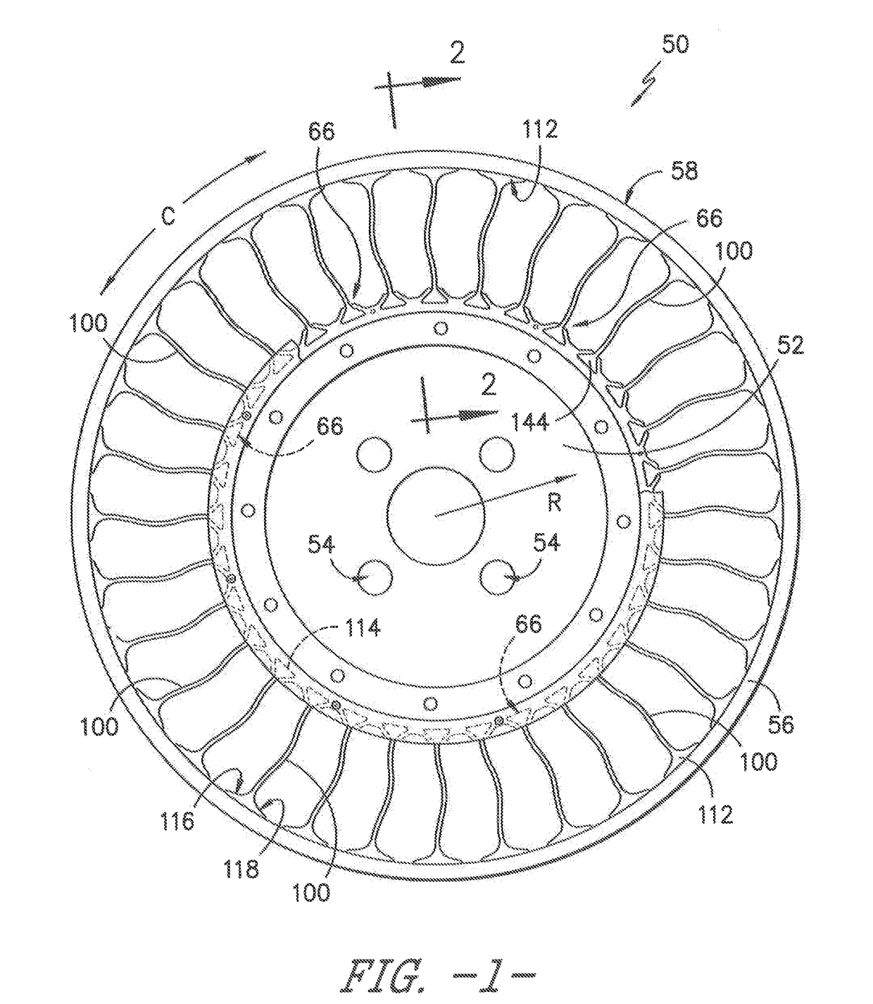
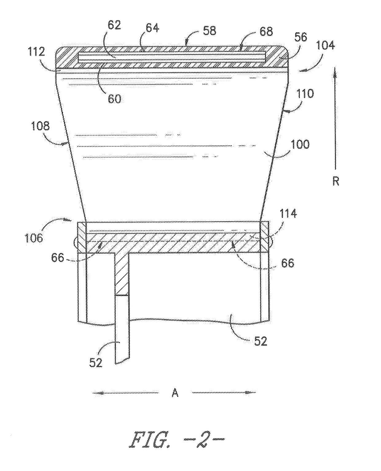
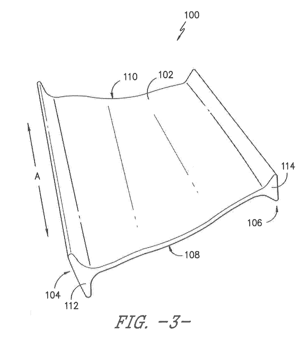
  • Spoke fabrication for a non-pneumatic wheel
  • Spoke fabrication for a non-pneumatic wheel
  • Spoke fabrication for a non-pneumatic wheel

Examples


Embodiment Construction

[0026]For purposes of describing the invention, reference now will be made in detail to embodiments of the invention, one or more examples of which are illustrated in the drawings. Each example is provided by way of explanation of the invention, not limitation of the invention. In fact, it will be apparent to those skilled in the art that various modifications and variations can be made in the present invention without departing from the scope or spirit of the invention. For instance, features illustrated or described as part of one embodiment, can be used with another embodiment to yield a still further embodiment. Thus, it is intended that the present invention covers such modifications and variations as come within the scope of the appended claims and their equivalents.

[0027]As used herein, the following definitions apply.

[0028]Axial direction A refers to a direction parallel to an axis about which a referenced exemplary wheel rotates during use.

[0029]Radial direction R refers to...


PUM

PropertyMeasurementUnit
Temperatureaaaaaaaaaa
Pressureaaaaaaaaaa
Pressureaaaaaaaaaa

Abstract

An exemplary method of manufacture for a spoke (100) of a non-pneumatic wheel. The spoke can be manufactured with a reinforcement structure having reinforcement elements and one or more layers of material. The spoke can also be provided in various shapes and configurations. The spoke includes anchors (112, 114) that allow the spoke to be more readily incorporated into, or removed from, a non-pneumatic wheel. More particularly, the anchors also allow the spoke to be joined as one-piece with the non-pneumatic wheel or releasably connected on one or both ends with the non-pneumatic wheel.

Description

FIELD OF THE INVENTION[0001]The present invention relates to a method of manufacture for a non-pneumatic wheel.BACKGROUND OF THE INVENTION[0002]Non-pneumatic wheel constructions and their benefits are described in e.g., U.S. Pat. Nos. 6,769,465; 6,994,134; 7,013,939; and 7,201,194, which are incorporated herein by reference in their entirety. Some non-pneumatic tire constructions propose incorporating a shear band, embodiments of which are described in e.g., U.S. Pat. Nos. 6,769,465 and 7,201,194. Such non-pneumatic tires provide advantages in tire performance without relying upon a gas inflation pressure for support of the loads applied to the tire.[0003]In one example of a non-pneumatic wheel, a compliant band with a ground contacting portion can be connected with a plurality of tension-transmitting, web-like elements (i.e. spokes) extending radially from a center element or hub. For certain constructions, such non-pneumatic wheel may be formed by open cast molding in which a mate...

Claims


Application Information

Patent Timeline
IPC IPC(8): B29D30/02B60C7/14B29C70/76
CPCB29D30/02B60C7/14B29C70/76B60C2007/146B29K2995/0077B29K2075/00B29K2083/00B60B5/02B60B9/04B60B31/00B60C7/146
Inventor DELFINO, ANTONIOBERGUERAND, PHILIPPESCHROETER, PASCALBLANC, MAEIKE
Owner MICHELIN & CO CIE GEN DES ESTAB MICHELIN
Learn More