Liquid ejecting apparatus and maintenance method for liquid ejecting apparatus

Active Publication Date: 2018-12-06
SEIKO EPSON CORP
View PDF6 Cites 0 Cited by
  • Summary
  • Abstract
  • Description
  • Claims
  • Application Information

AI Technical Summary

Benefits of technology

The invention provides a liquid ejecting apparatus and a method to maintain it. The advantage is that it allows for better maintenance of the ejection unit.

Problems solved by technology

Therefore, the maintenance cannot be performed appropriately.

Method used


Image

  • Liquid ejecting apparatus and maintenance method for liquid ejecting apparatus
  • Liquid ejecting apparatus and maintenance method for liquid ejecting apparatus
  • Liquid ejecting apparatus and maintenance method for liquid ejecting apparatus

Examples


first embodiment

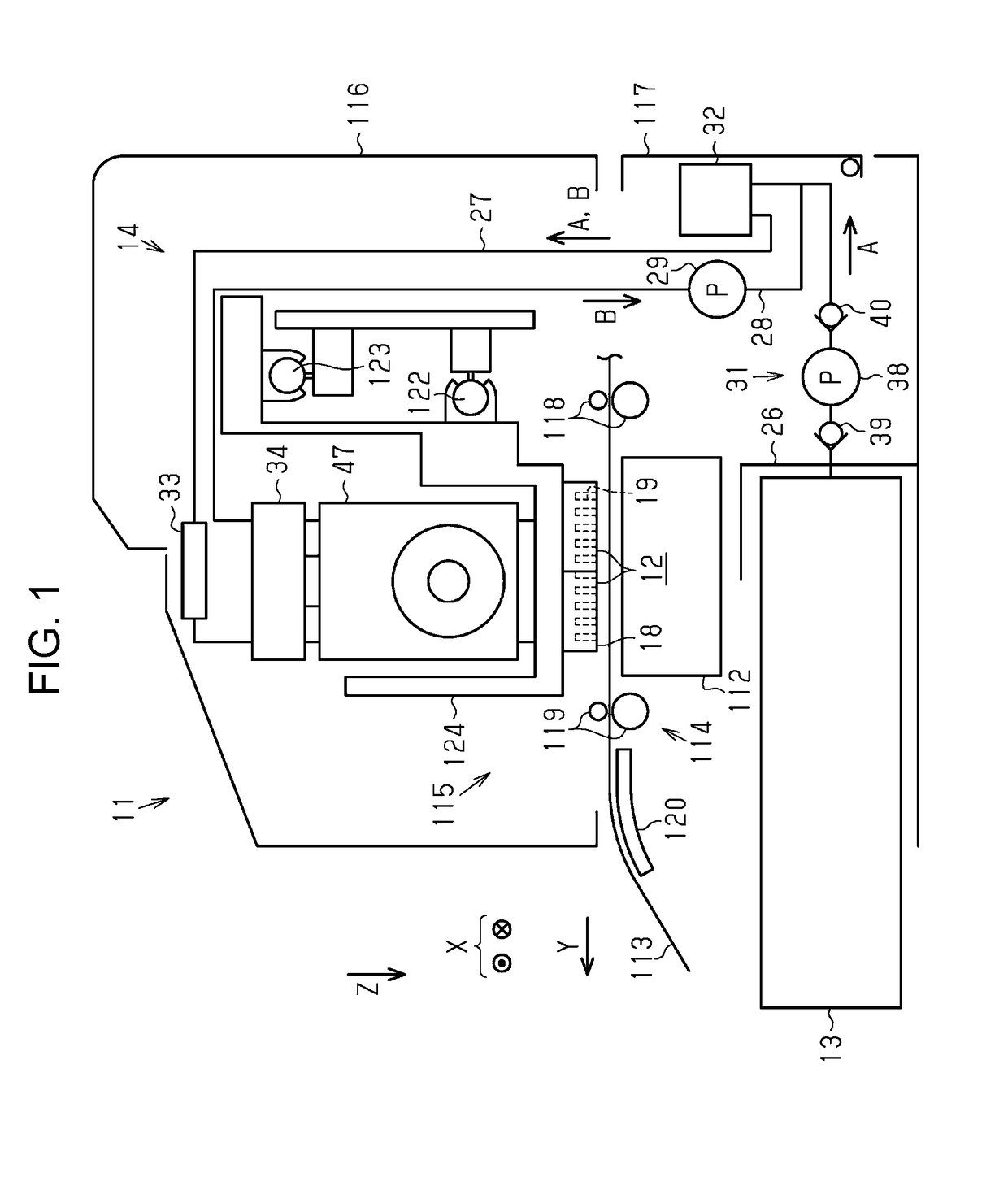
[0028]As illustrated in FIG. 1, a liquid ejecting apparatus 11 includes liquid ejecting units 12 that eject liquid and a supply mechanism 14 that supplies liquid from a liquid supply source 13 to the liquid ejecting units 12. Furthermore, the liquid ejecting apparatus 11 includes a supporting table 112 that is disposed at a position facing the liquid ejecting units 12, a transporting unit 114 that transports a medium 113 in a transportation direction Y, and a printing unit 115 that performs printing by ejecting liquid onto the medium 113 with the liquid ejecting units 12 moving in a scanning direction X.

[0029]The supporting table 112 extends in a width direction of the medium 113 (the scanning direction X) that is a direction orthogonal to (intersecting) the transportation direction Y of the medium 113. The supporting table 112, the transporting unit 114, and the printing unit 115 are assembled into a main body 116 that is configured of a housing, a frame, or the like. The main body...

second embodiment

[0133]Next, a second embodiment of the liquid ejecting apparatus 11 will be described with reference to drawings.

[0134]The second embodiment is obtained by changing the pressure adjustment device 47 in the first embodiment to a pressure adjustment device 200 as illustrated in FIGS. 10 and 11 and the second embodiment is the same as the first embodiment in other aspects. Therefore, the same members are given the same reference numerals and the repetitive description thereof will be omitted.

[0135]As illustrated in FIGS. 10 and 11, the pressure adjustment device 200 is formed by assembling an air chamber forming unit 201, a pressure adjustment mechanism forming unit 202, a bottom plate member 203, a connection portion forming unit 204, and two lever units 205.

[0136]The connection portion forming unit 204 includes a main body portion 206 and a connection film 207 that is attached such that the connection film 207 covers an outer surface of the main body portion 206. A first liquid conne...


PUM


Abstract

A liquid ejecting apparatus includes a liquid ejecting unit provided with a nozzle from which liquid is ejected, a liquid supply flow path connected to a liquid supply source and the liquid ejecting unit, and a pump mechanism that includes a pump chamber provided in the liquid supply flow path and that repeats a suction driving operation and a discharge driving operation such that the liquid flows toward the liquid ejecting unit from the liquid supply source. Before maintenance of the liquid ejecting unit is performed by discharging liquid from the nozzle, the pump mechanism performs the suction driving operation until the amount of liquid accommodated in the pump chamber reaches a set value, which is set in advance.

Description

BACKGROUND1. Technical Field[0001]The present invention relates to a liquid ejecting apparatus such as a printer and a maintenance method for a liquid ejecting apparatus.2. Related Art[0002]There is a liquid ejecting apparatus that is provided with a liquid ejecting head including a nozzle from which liquid is ejected and a pump supplying liquid to the liquid ejecting head by repeating a suction driving operation and a discharge driving operation (for example, JP-A-2009-160912).[0003]It is possible to perform maintenance of a liquid ejecting head by supplying liquid and discharging liquid from a nozzle with a pump performing a discharge driving operation. In this case, if the amounts of liquid accommodated in pump chambers are different from each other at a time when the pump starts the discharge driving operation, the way in which liquid flows does not become constant at the time of the discharge driving operation thereafter. Therefore, the maintenance cannot be performed appropria...

Claims


Application Information

Patent Timeline
IPC IPC(8): B41J2/175
CPCB41J2/17596B41J2/16535B41J2/1714B41J2/175B41J2/18B41J2002/1655
Inventor UDAGAWA, TOMOKI
Owner SEIKO EPSON CORP
Why Eureka
Try Eureka