Current sensor and measuring apparatus

Active Publication Date: 2017-11-23
HIOKI DENKI KK
View PDF3 Cites 6 Cited by
  • Summary
  • Abstract
  • Description
  • Claims
  • Application Information

AI Technical Summary

Benefits of technology

The current sensor and measuring apparatus described in the patent text have a gap that increases the magnetoresistance of a closed magnetic circuit, which prevents magnetic saturation even at high current levels. The internal shield member effectively covers the magnetic core, magneto-electric converter, and coils, reducing the effect of external magnetic fields. Additionally, the external shield member is positioned outside the internal shield member to further reduce the impact of external magnetic fields and maintain favorable linearity. This results in higher accuracy of current measurement.

Problems solved by technology

This means that with this current sensor, magnetic flux leaks from these parts toward the magnetic shield case.
Accordingly, for the measuring apparatus that uses this current sensor, there is a problem that in a state where the current flowing in the wire to be measured reaches a large current region where magnetic saturation occurs for the magnetic shield case, the detection sensitivity increases (that is, linearity of the detection sensitivity is lost).

Method used


Image

  • Current sensor and measuring apparatus
  • Current sensor and measuring apparatus
  • Current sensor and measuring apparatus

Examples


Embodiment Construction

[0044]Embodiments of a current sensor and a measuring apparatus will now be described with reference to the attached drawings.

[0045]First, the configuration of a current sensor 1 will be described.

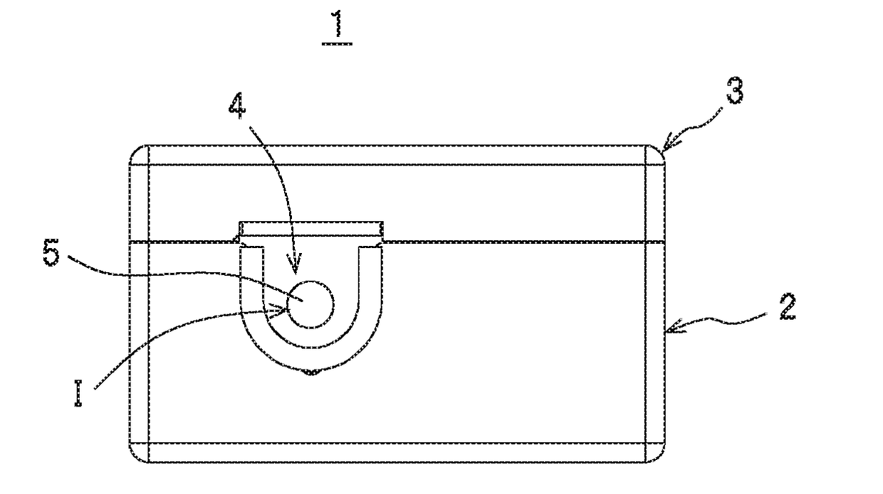
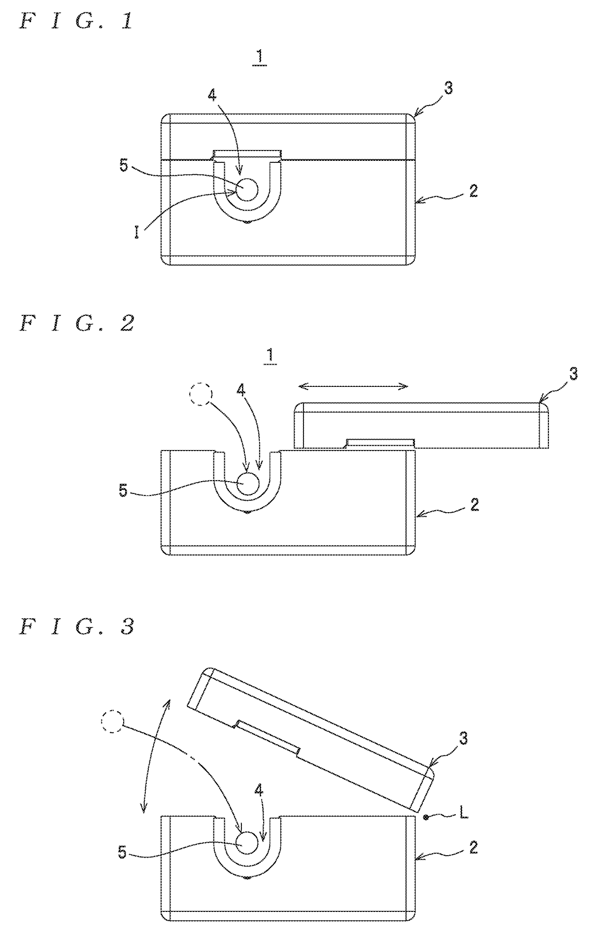
[0046]As depicted for example in FIG. 1, the current sensor 1 includes a first core unit 2 and a second core unit 3 that is supported by an opening / closing mechanism, not illustrated, so as to be capable of opening and closing the first core unit 2, and is configured so as to be capable of enclosing (clamping) a measured electrical path 5, which has been introduced into a concave channel (or “window”) 4 formed in the first core unit 2, between the core units 2 and 3. Here, regarding the opening / closing mechanism, as depicted in FIG. 2, it is possible to slide (linearly move) the second core unit 3 relative to the first core unit 2 as the opening / closing mechanism, and as depicted in FIG. 3, it is also possible to rotate the second core unit 3 relative to the first core unit 2 about a rotat...


PUM


Abstract

There is provided a ring-shaped magnetic core that forms a closed magnetic circuit that encloses a measured electrical path, a magneto-electric converter that detects magnetic flux inside the magnetic core and outputs an electrical signal with an amplitude in keeping with a quantity of the magnetic flux, a coil that is formed on the magnetic core and is supplied with a negative feedback current generated based on the electrical signal, and an internal shield member disposed at least in a vicinity of the magneto-electric converter and the coil. A first gap that increases a magnetoresistance of a closed magnetic circuit, which is a closed magnetic circuit for leakage flux that leaks from the magnetic core and includes the internal shield member, a part of the magnetic core where the coil is formed, and the magneto-electric converter, is formed in the internal shield member.

Description

TECHNICAL FIELD[0001]The present invention relates to a current sensor, which is equipped with a magnetic core, a magneto-electric converter such as a Hall element, a coil formed on the magnetic core, and a shield member (such as a shield case) and is configured so that the magnetic core forms a closed magnetic circuit that encloses a measured electrical path, and to a measuring apparatus equipped with such current sensor.BACKGROUND ART[0002]One example of a current sensor of this type is a current sensor that has already been disclosed by the present applicant in Patent Document 1 indicated below. The current sensor in the cited document has the following basic configuration. The current sensor includes a magnetic core configured so as to be split into a fixed first magnetic core and a movable (openable) second core so that a wire to be measured can be passed through an internal void, and a magnetic shield case (composed of a fixed first magnetic shield case and a movable second ma...

Claims


Application Information

Patent Timeline
IPC IPC(8): G01R15/14
CPCG01R15/148G01R15/207
Inventor YOKOTA, OSAMUMASUDA, HIDEKAZU
Owner HIOKI DENKI KK
Why Eureka
Try Eureka