Magnetic core for current sensor having high magnetic saturation

Inactive Publication Date: 2009-01-08
DENSO CORP
View PDF4 Cites 19 Cited by
  • Summary
  • Abstract
  • Description
  • Claims
  • Application Information

AI Technical Summary

Benefits of technology

[0010]The magnetic core is formed by laminating magnetic core layers (e.g., two layers) in a direction from an inside to an outside of the magnetic core. The content ratio of the magnetic material is made higher in the outer layer than in the inner layer. In this manner, a flux density in the magnetic core is made uniform because the density of the magnetic flux becomes higher in the inside portion if the content ratio of the magnetic material is uniform. Alternatively, the magnetic core is formed by laminating plural magnetic core layers, each having s different magnetic material content ratio, in the thickness direction. In this manner, a degree of magnetic saturation in the magnetic core is easily adjusted to a desired level.
[0012]The magnetic core may be subjected to weather-resistive surface treatment after it is molded to improve its weather resistance. Glass fibers may be added to the resin material to improve a mechanical strength of the magnetic core. The molding process of the magnetic core may be performed under a magnetic field to direct grain crystals in the same direction.

Problems solved by technology

Following problems, however, are involved in the conventional current sensor disclosed in JP-A-2002-296305.
A size of the magnetic core is relatively large in an entire current sensor, and therefore it has been difficult to make the current sensor compact.

Method used


Image

  • Magnetic core for current sensor having high magnetic saturation
  • Magnetic core for current sensor having high magnetic saturation
  • Magnetic core for current sensor having high magnetic saturation

Examples


first embodiment

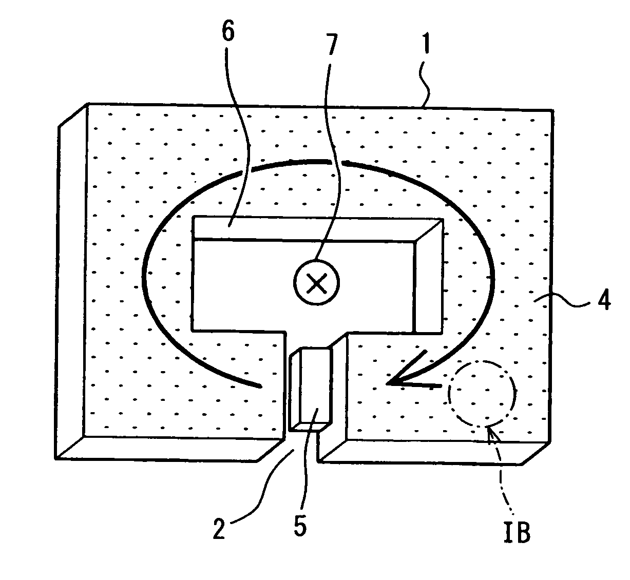
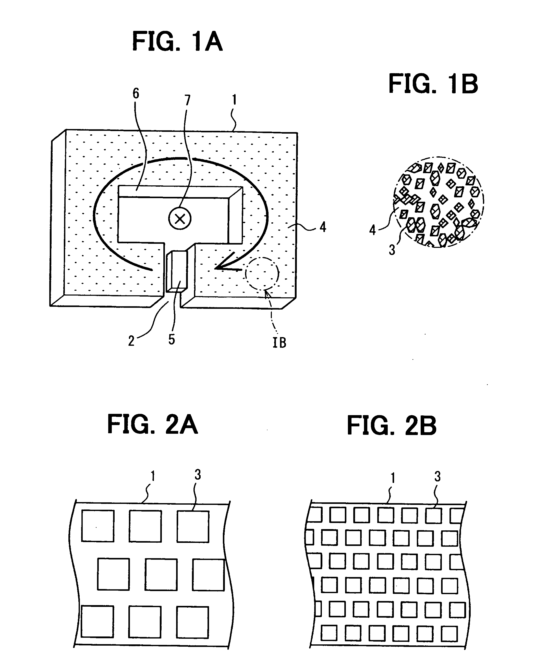
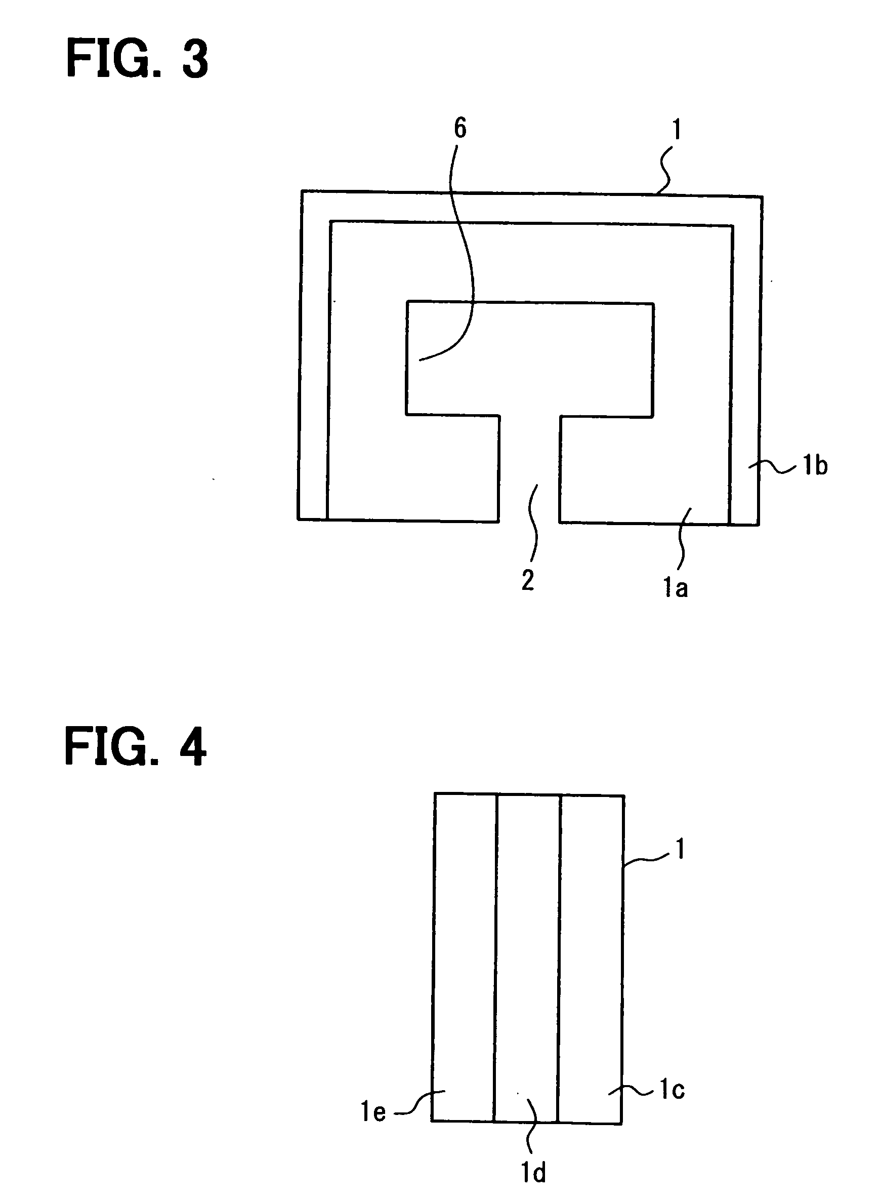
[0022]the present invention will be described with reference to FIGS. 1A-2B. As shown in FIG. 1A, the magnetic core 1 is formed in a rectangular shape having a gap 2. The magnetic core 1 is formed by injection molding. The material forming the magnetic core 1 is a resin material that contains granular soft magnetic material such as permalloy. As shown in FIG. 1B, the granular soft magnetic material 3 is dispersed in the resin material 4. If a higher mechanical strength of the magnetic core 1 is required, glass fibers may be added to the resin material.

[0023]A conductor 7 is positioned in a through-hole 6 formed in the magnetic core 1. Magnetic flux is generated in the magnetic core 1 according to an amount of electric current flowing through the conductor 7. The amount of magnetic flux is measured by a Hall element 5 fixedly disposed in the gap 2. Thus, the amount of current flowing through the conductor 7 is detected by the Hall element 5. Current sensors other than the Hall elemen...

fourth embodiment

[0031]FIG. 5 shows the present invention. In this embodiment, the magnetic core 1 is subjected to weather-resistive surface treatment after it is molded. Accordingly, the surface of the magnetic core 1 is covered with a weather-resistive layer. Other structures and functions are the same as those of the foregoing embodiments.

fifth embodiment

[0032]FIG. 6 shows the present invention. In this embodiment, the magnetic core 1 is molded under a magnetic filed imposed thereon. By imposing the magnetic field in the molding process, crystal directions of the grains of the soft magnetic material can be made uniform thereby to improve core characteristics.


PUM


Abstract

A magnetic core according to the present invention is used in a current sensor for detecting amount of current flowing through a conductor by a Hall element. The magnetic core is made of a resin material, in which a granular magnetic material is dispersed, and is shaped to form a circular magnetic flux passage therein by injection molding. The magnetic core is formed by laminating plural layers in an inside to outside direction of the magnetic core, and a magnetic material content is made higher in the outer layers than in the inner layers. In this manner, uniformity of the magnetic flux density in the core is improved. Alternatively, the magnetic core is made by laminating plural layers having respective magnetic material content ratios in its thickness direction to adjust magnetic saturation to a desired level. A measurable range of electric current is widened by suppressing magnetic saturation in the magnetic core without increasing its size.

Description

CROSS-REFERENCE TO RELATED APPLICATION[0001]This application is based upon and claims benefit of priority of Japanese Patent Application No. 2007-177382 filed on Jul. 5, 2007, the content of which is incorporated herein by reference.BACKGROUND OF THE INVENTION[0002]1. Field of the Invention[0003]The present invention relates to a magnetic core for use in a current sensor that detects an amount of current by Hall element based on magnetic flux generated in the magnetic core by electric current.[0004]2. Description of Related Art[0005]An example of a current sensor that uses a Hall element is disclosed in JP-A-2002-296305. A magnetic core is formed in a circular shape having a gap by laminating three magnetic core plates made of a magnetic material. A through-hole is made in the center of the magnetic core, and a Hall element for detecting an amount of magnetic flux in the magnetic core is disposed in the gap.[0006]Following problems, however, are involved in the conventional current ...

Claims


Application Information

Patent Timeline
IPC IPC(8): H01F27/24G01R15/20
CPCG01R15/207G01R15/202
Inventor ISHIHARA, MASATO
Owner DENSO CORP
Why Eureka
Try Eureka