Defect inspection apparatus for tubular product such as intermediate transfer belt

a technology of defect inspection apparatus and tubular product, which is applied in the direction of electrographic process, image enhancement, instruments, etc., can solve the problems of low defect detection accuracy, adversely affecting the quality and the absence of defects on the outer surface of the intermediate transfer belt when inspected, so as to improve the defect detection accuracy

Inactive Publication Date: 2018-12-13
KONICA MINOLTA INC
View PDF5 Cites 6 Cited by
  • Summary
  • Abstract
  • Description
  • Claims
  • Application Information

AI Technical Summary

Benefits of technology

[0010]The present invention is directed to solve the above problems, and an object thereof is to provide a defect inspection apparatus capable of improving defect detection accuracy.

Problems solved by technology

However, in the prior art, only the presence or absence of a defect in the outer surface of the intermediate transfer belt was inspected.
For this reason, the conventional technique has a problem that the defect detection accuracy is low.
The defect of the inner surface of the intermediate transfer belt may also adversely affect the quality of the intermediate transfer belt.
The problem of low defect detection accuracy was not only when the inspection target was an intermediate transfer belt but also when the inspection target was a tubular product.

Method used


Image

  • Defect inspection apparatus for tubular product such as intermediate transfer belt
  • Defect inspection apparatus for tubular product such as intermediate transfer belt
  • Defect inspection apparatus for tubular product such as intermediate transfer belt

Examples


second embodiment

[0096]FIG. 12 is a front view showing the structure of a defect inspection apparatus 100a according to the second embodiment of the present invention.

[0097]Referring to FIG. 12, as a configuration for photographing the outer surface 1a, the defect inspection apparatus 100a in the present embodiment includes a plurality of light sources 31a and 31b, a plurality of line cameras 32a and 32b, and a plurality of lenses 33a and 33b.

[0098]The light sources 31a and 31b are arranged along the central axis CX (in the vertical direction) and are fixed to the arm 22. The line cameras 32a and 32b are arranged along the central axis CX (in the vertical direction) and fixed to the arm 22. The lenses 33a and 33b are arranged along the central axis CX (in the vertical direction) and are fixed to the arm 22.

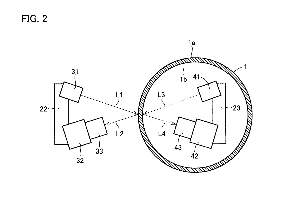
[0099]The light source 31a irradiates the area RG1 on the upper part of the outer surface 1a of the rotating intermediate transfer belt 1. The line camera 32a receives reflected light from the ar...

third embodiment

[0105]FIG. 13 is a front view showing the structure of a defect inspection apparatus 100b according to the third embodiment of the present invention.

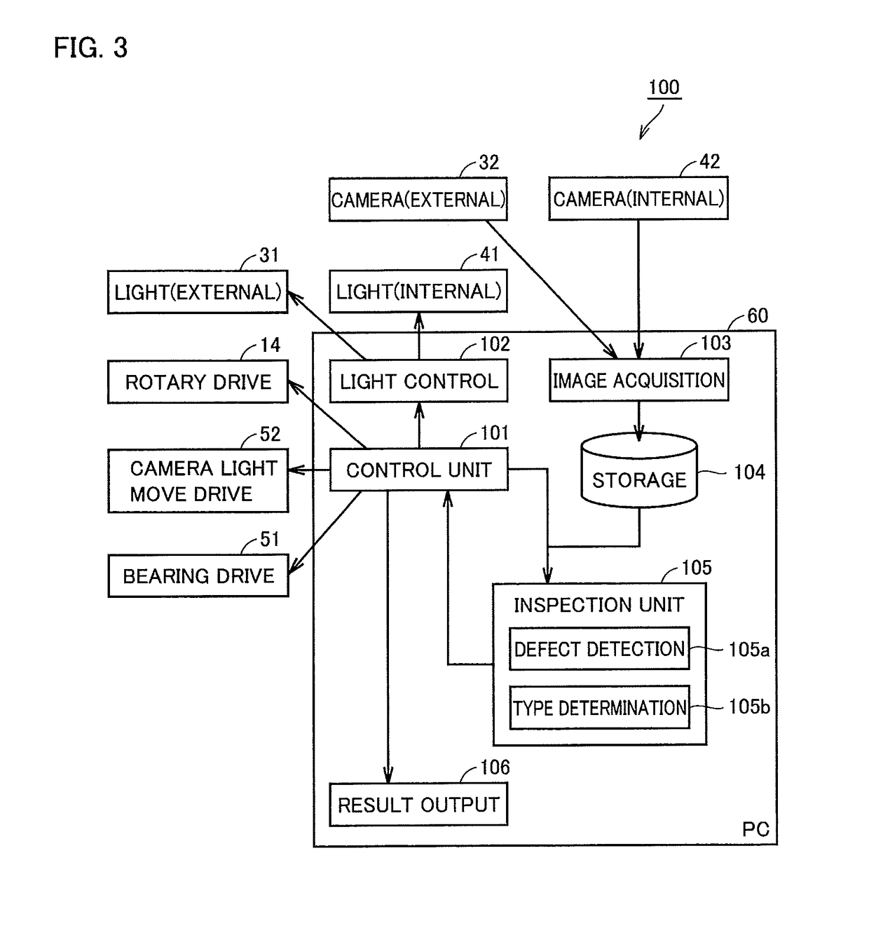
[0106]Referring to FIG. 13, in the defect inspection apparatus 100b in the present embodiment, the bearing 12 and the rotating rail 13 are fixed to the frame 20. The upper surface of the rotating rail 13 is in contact with the lower surface of the main body part 21 of the frame 20. With this, the camera light source movement drive unit 52 is able to move the bearing 12 and the rotating rail 13 along the central axis CX, together with frame 20, light sources 31a, 31b, 41a, and 41b, line cameras 32a, 32b, 42a, and 42b and lenses 33a, 33b, 43a, and 43b.

[0107]Next, the operation of the defect inspection apparatus 100b in the present embodiment will be described.

[0108]The camera light source movement drive unit 52 raises the bearing 12 and the rotating rail 13 together with the frame 20 and so on. Above the top of the rotary table 11, the c...

fourth embodiment

[0116]FIG. 15 is a front view showing the structure of a defect inspection apparatus 100c according to the fourth embodiment of the present invention.

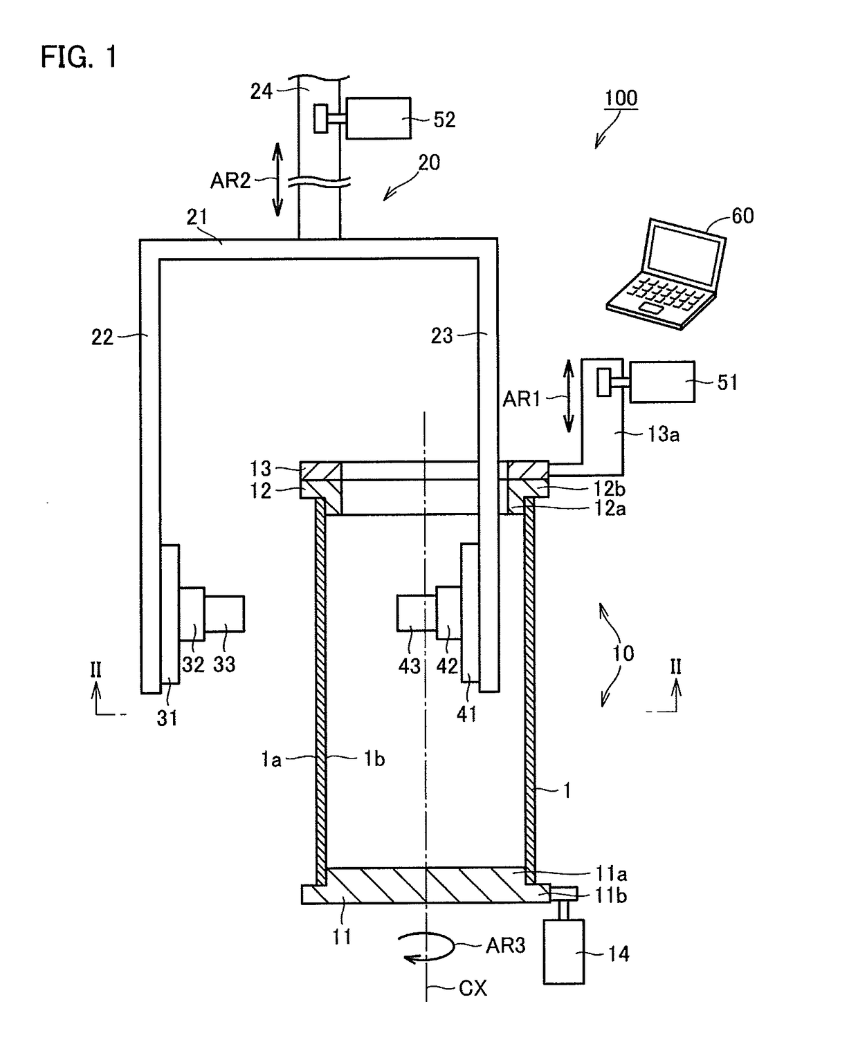
[0117]Referring to FIG. 15, in the defect inspection apparatus 100c of the present embodiment, frame 20 includes arms 22 and 23 not connected to each other and does not include main body part 21 and extending part 24 (FIG. 1). The light source 31, the line camera 32, and the lens 33 are fixed to the arm 22. The light source 41, the line camera 42, and the lens 43 are fixed to the arm 23.

[0118]The camera light source movement drive unit 52 also includes two camera light source movement drive units 52a and 52b. By applying power to the arm 22, as indicated by an arrow AR 21, the camera light source movement drive unit 52a moves the arm 22, the light source 31, the line camera 32, and the lens 33 along the central axis CX (in the vertical direction). By applying power to the arm 23, as indicated by an arrow AR 22, the camera light source ...


PUM

PropertyMeasurementUnit
RGaaaaaaaaaa
RGaaaaaaaaaa
RGaaaaaaaaaa

Abstract

A defect inspection apparatus comprises a light source that irradiates the outer surface of the intermediate transfer belt, a first line camera for receiving the light from the outer surface and transmitting a signal based on the received light, a light source that irradiates the inner surface of the intermediate transfer belt, and a second line camera that receives the light from the inner surface and transmits a signal based on the received light. Based on the signal received from the first line camera, the defect inspection apparatus creates an outer surface image of the outer surface. Based on the signal received from the second line camera, the defect inspection apparatus creates an inner surface image of the inner surface. Based on the outer surface image and the inner surface image, the defect inspection apparatus detects defects contained in the intermediate transfer belt.

Description

[0001]The entire disclosure of Japanese patent application No. 2017-115615 filed on Jun. 13, 2017, is incorporated herein by reference in its entirety.BACKGROUNDTechnological Field[0002]The present invention relates to a defect inspection apparatus. More specifically, the present invention relates to a defect inspection apparatus for a tubular product capable of improving defect detection accuracy.Description of the Related Art[0003]Electrophotographic image forming apparatuses include MFPs (Multi Function Peripherals), facsimile machines, copying machines, printers, and so on. The MFP has a scanner function, a facsimile function, a copying function, a function as a printer, a data communication function, and a server function.[0004]An image forming apparatus generally develops an electrostatic latent image formed on an image carrying member with a developing device to form a toner image. The image forming apparatus transfers the toner image to the sheet and then fixes the toner ima...

Claims


Application Information

Patent Timeline
Patent Type & Authority Applications(United States)
IPC IPC(8): G06T7/00G01N21/88G01N21/954G03G15/00
CPCG06T7/0004G01N21/8851G01N21/954G03G15/5054G01N2021/9548G03G2215/00059G01N21/8806G01N21/952G01N2021/8854G01N2021/8887G06T2207/30164
Inventor KUWASAKO, MASAHIRO
Owner KONICA MINOLTA INC
Why Eureka
Try Eureka