Thermal plastic elastomer injection mold, water impervious slide fastener manufactured utilizing the same and finished product having the water impervious slide fastener
a technology of thermoplastic elastomer and injection mold, which is applied in the direction of haberdashery, coatings, other domestic articles, etc., can solve the problems of affecting the service life of the inability to fully serve or even provide the whole waterproof effect and the inability to open and close the operation of the slide fastener. it is not easy to clean,
- Summary
- Abstract
- Description
- Claims
- Application Information
AI Technical Summary
Benefits of technology
Problems solved by technology
Method used
Image

Examples
first embodiment
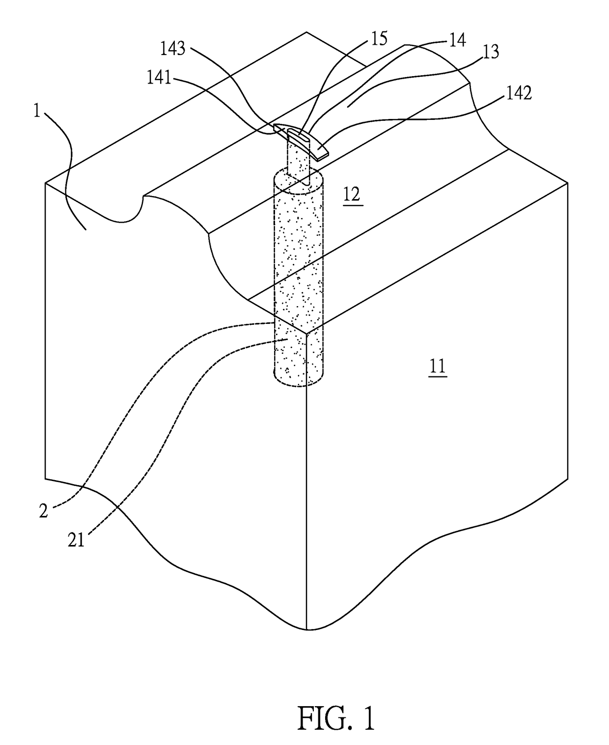
[0023]Please refer to FIG. 1, which is a perspective view illustrating a thermal plastic elastomer injection mold 1 according to the present invention. As shown in FIG. 1, the thermal plastic elastomer injection mold 1 includes a mold base 11, the mold base 11 is formed with a slide fastener supporting platform 12 having a top surface thereof formed with an arc-shaped surface 13, the arc-shaped surface 13 is transversally and protruding formed with an elongated arc-shaped ridge 14, and two ends of the arc-shaped ridge 14 are respectively formed with a front end 141 and a rear end 142, a substantial central location of the arc-shaped ridge 14 is longitudinally formed with a thermal plastic elastomer injection port 15 connected to at least one extruder 2. The width and the height of the arc-shaped ridge 14 and the dimension of the thermal plastic elastomer injection port 15 are determined with respect to the size of a slide fastener, and the thermal plastic elastomer injection mold 1 ...
second embodiment
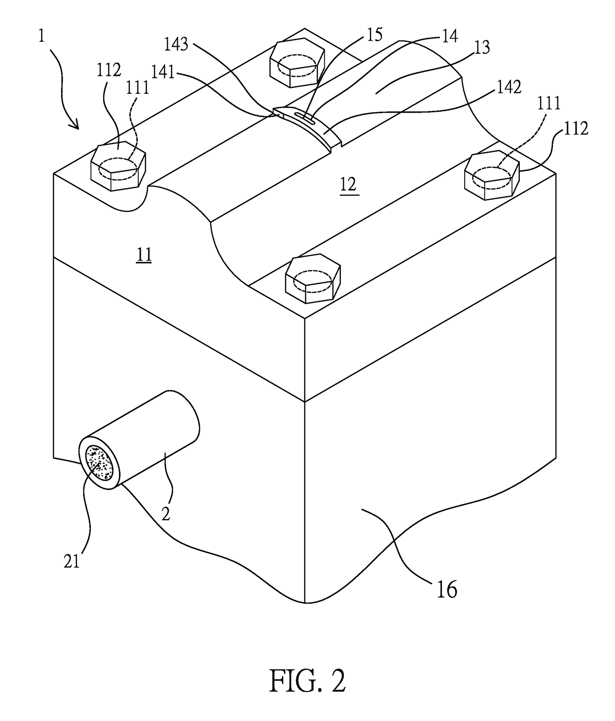
[0024]Please refer to FIG. 2, which is a perspective view illustrating the thermal plastic elastomer injection mold 1 according to the present invention. For satisfying different thermal plastic elastomer injection requirements of slide fasteners with various sizes, the thermal plastic elastomer injection mold 1 further includes a fasten seat 16, adjacent surfaces of the fasten seat 16 and the mold base 11 are correspondingly formed with at least one fasten hole, for example a screw hole (not shown in figures because of projection angle) and at least one connection hole 111, for example a stepped penetrated hole, and a connection member 112, for example a screw rod, is allowed to pass each of the connection holes 111 and locked in each of the fasten holes, so that the mold base 11 can be assembled with the fasten seat 16, or the mold base 11 can be disassembled with the fasten seat 16.
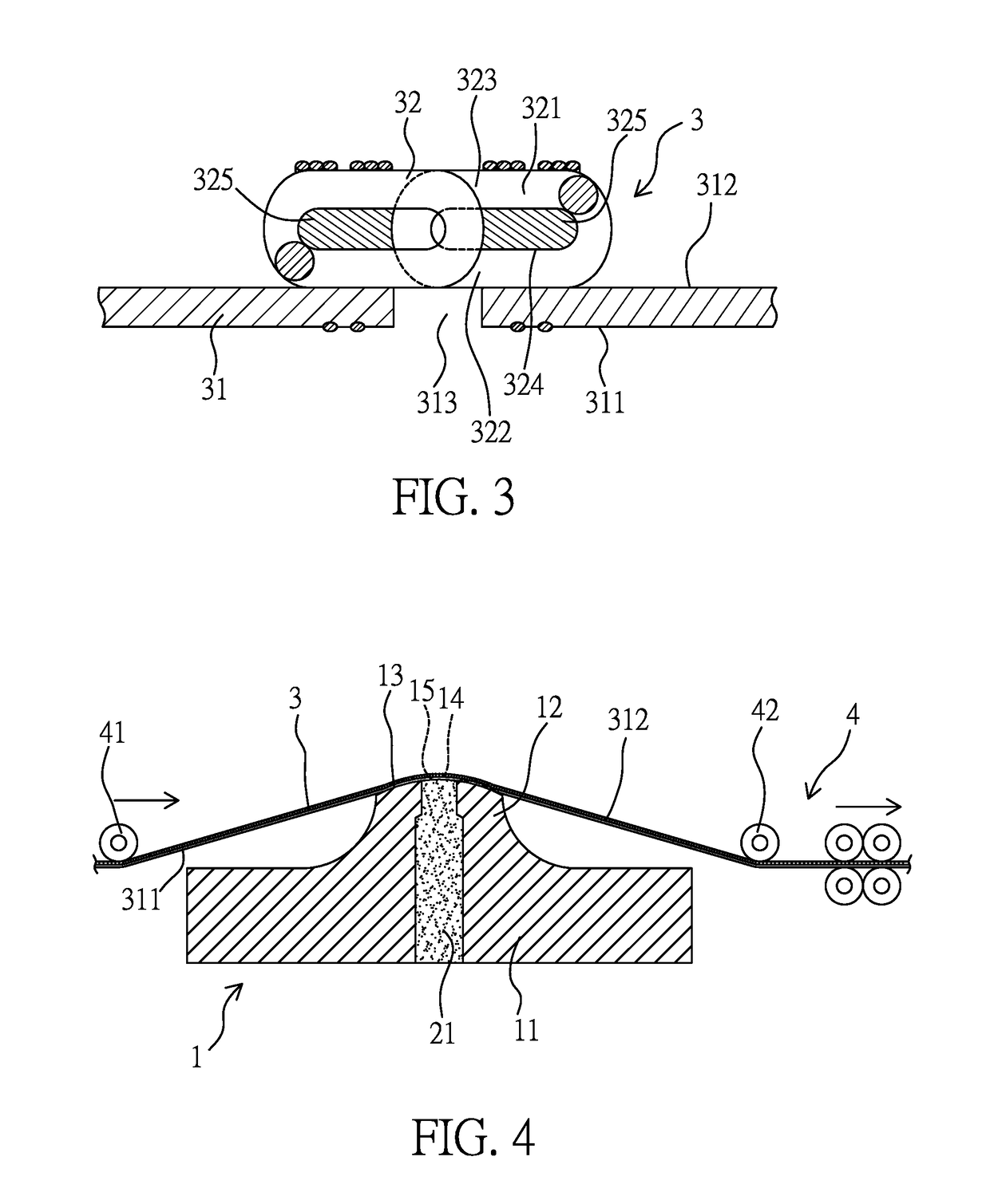
[0025]Please refer to FIG. 3, which is a cross sectional view illustrating a slide fastener 3, wher...
third embodiment
[0035]Please refer to FIG. 7, which is a cross sectional view illustrating the slide fastener after being processed with the thermal plastic elastomer injection operation by utilizing the thermal plastic elastomer injection mold 1 according to the present. Because the arc-shaped ridge 14 is installed with the inclined recess 151, and the rear end 142 is lower than the front end 141, and the thermal plastic elastomer 21 is filled in the slits 321 inside the adjacent coupling elements 32 and the gap 313 of the pair of support-tapes 31, when the rear guide wheel 42 is at a lower position, a distance between the thermal plastic elastomer 21 inside the gap 313 and the first surface 311 is substantially the same as the height of the rear end 142 of the arc-shaped ridge 14. As mentioned above, by adjusting the width of the arc-shaped ridge 14 and the injection power, when the thermal plastic elastomer 21 is injected into the gaps 313 and into the slits 321 of the coupling elements 32 and t...
PUM
| Property | Measurement | Unit |
|---|---|---|
| Width | aaaaa | aaaaa |
| Width | aaaaa | aaaaa |
| Time | aaaaa | aaaaa |
Abstract
Description
Claims
Application Information
 - R&D
- Intellectual Property
- Life Sciences
- Materials
- Tech Scout
- Unparalleled Data Quality
- Higher Quality Content
- 60% Fewer Hallucinations
Browse by: Latest US Patents, China's latest patents, Technical Efficacy Thesaurus, Application Domain, Technology Topic, Popular Technical Reports.
© 2025 PatSnap. All rights reserved.Legal|Privacy policy|Modern Slavery Act Transparency Statement|Sitemap|About US| Contact US: help@patsnap.com