Mechanical computer with repositionable components
a technology of mechanical computers and components, applied in the field of mechanical computing systems, can solve the problems of few tools to teach the computer itself, not how it works, and the difficulty of learning code for children
- Summary
- Abstract
- Description
- Claims
- Application Information
AI Technical Summary
Benefits of technology
Problems solved by technology
Method used
Image
Examples
case # 1
[0061]Case #1, wherein inputs A and B are both “false,” is depicted in FIG. 10A. In an XOR gate, when both inputs are false, the output should be false. The program begins at FIG. 9A, in which gear bit 500 (input A) starts pointed to the left (a logical false) and gear bit 501 (input B) also starts pointed to the left (a logical false).
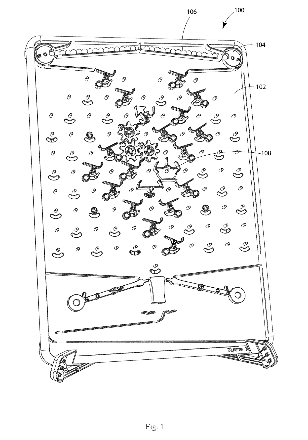
[0062]As depicted in FIG. 10B, when the left side incrementor 122 is depressed to start the program, a black colored unit 504 is released. The unit traverses through the flow path until it depresses the right side interceptor 122, thereby releasing a white colored unit 506. As depicted in FIG. 10C, the white colored unit 506 then traverses through the flow path to reach the interceptor 502.
case # 2
[0063]Case #2, wherein input A is “true” and input B is “false,” is depicted in FIG. 10D. In an XOR gate, when one input is true and the other is false, the output should be true. The program begins at FIG. 10D, in which gear bit 500 (input A) starts pointed to the right (a logical true) and gear bit 501 (input B) starts pointed to the left (a logical false). As depicted in FIG. 10E, when the left side incrementor 122 is depressed to start the program, a black colored unit 504 is released. The unit 504 traverses through the flow path to reach the interceptor 502.
case # 3
[0064]Case #3, wherein input A is “false” and input B is “true,” is depicted in FIG. 10F. In an XOR gate, when one input is true and the other is false, the output should be true. The program begins at FIG. 10F, in which gear bit 500 (input A) starts pointed to the left (a logical false) and gear bit 501 (input B) starts pointed to the right (a logical true). As depicted in FIG. 10G, when the left side incrementor 122 is depressed to start the program, a black colored unit 504 is released. The unit 504 traverses through the flow path to reach the interceptor 502.
PUM
 Abstract
Description
Claims
Application Information
 - R&D
- Intellectual Property
- Life Sciences
- Materials
- Tech Scout
- Unparalleled Data Quality
- Higher Quality Content
- 60% Fewer Hallucinations
Browse by: Latest US Patents, China's latest patents, Technical Efficacy Thesaurus, Application Domain, Technology Topic, Popular Technical Reports.
© 2025 PatSnap. All rights reserved.Legal|Privacy policy|Modern Slavery Act Transparency Statement|Sitemap|About US| Contact US: help@patsnap.com


