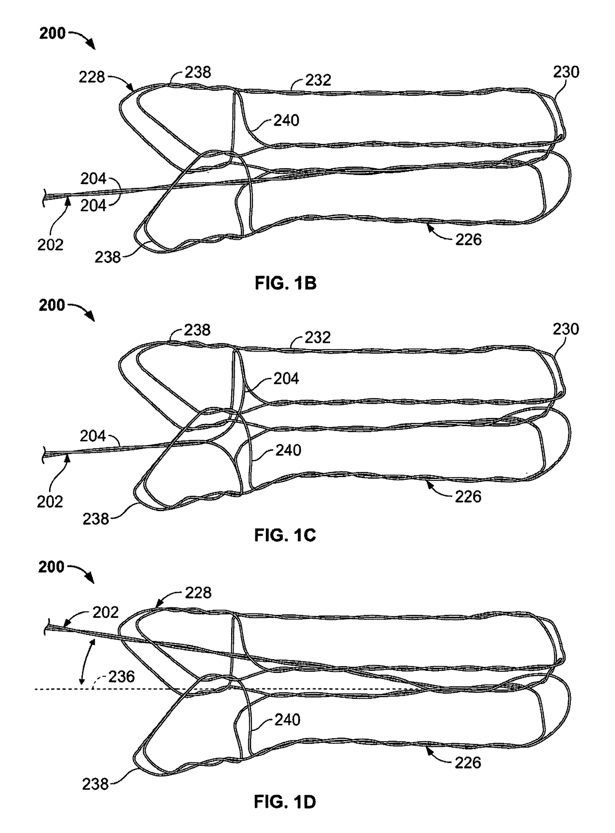
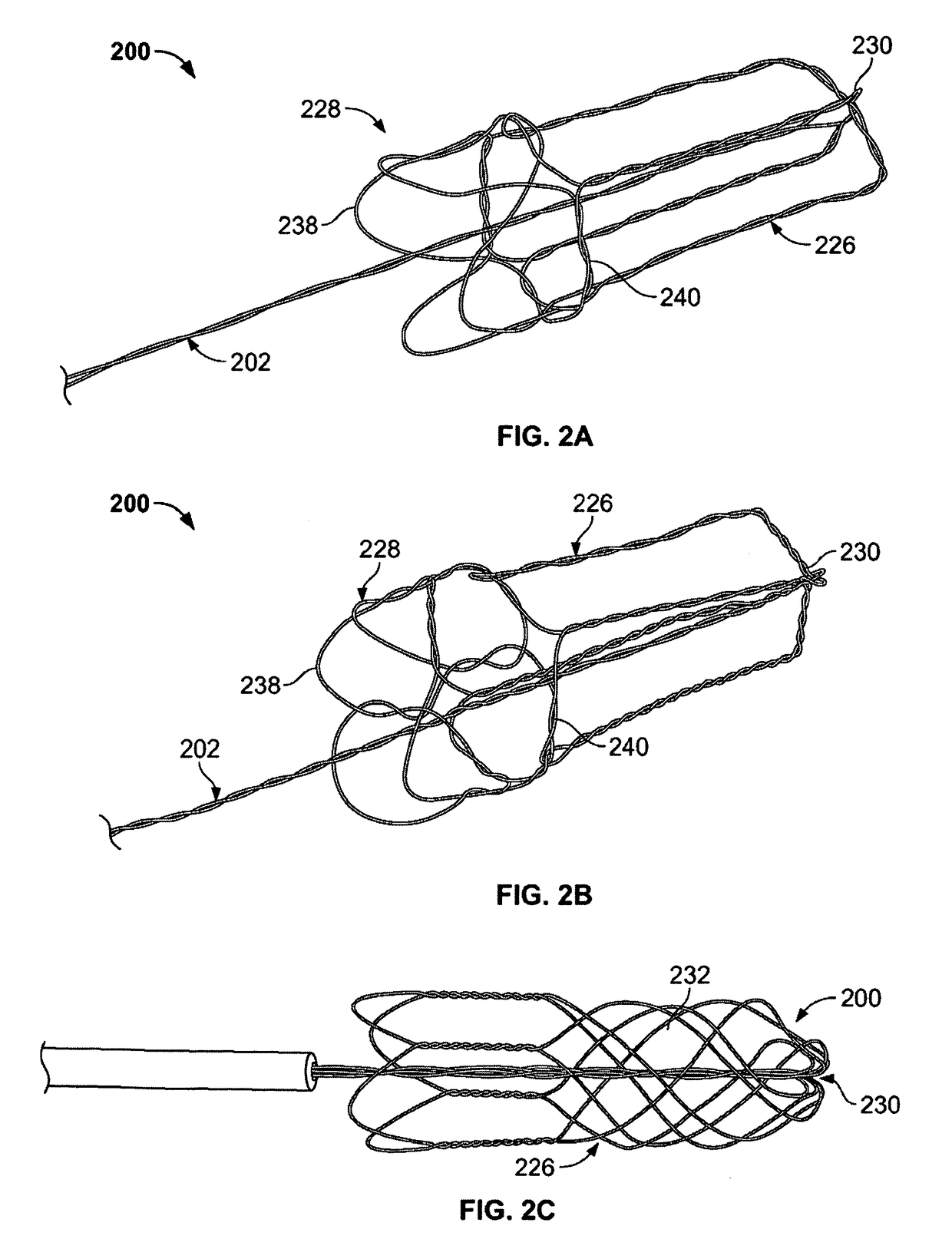
[0009]In one variation, the device includes a main bundle comprising one or a group of wires. The device also includes a capturing portion formed by the wires or wire of the main bundle. The capturing portion includes a cavity or space that is able to surround the obstruction. Accordingly, the capturing portion includes an open proximal end, a permeable distal end, and a capturing surface extending therebetween. The permeable distal end should be sufficiently permeable to allow blood to flow but have sufficient surface area to prevent escape of the obstruction or to prevent particles such as pieces of clot or emboli that would otherwise cause a complication if such pieces migrate through the body. In some variations of the device, the capturing portion is formed from the group of wires such that the group of wires diverges from the second end of the main bundle to form the permeable distal end, the group of wires extend back in a proximal direction to form the capturing surface and open proximal end about the main bundle, such that articulation of the capturing portion relative to the main bundle does not cause the open proximal end to reduce in size. Although some closing of the open proximal end can occur, it will not be sufficient to interfere with the obstruction as the capturing portion moves over the obstruction. In some variations, the permeable end may be the distal end or be towards the distal end (meaning anywhere past a proximal end). The terms distal and proximal are relative to the physician (e.g., the distal end is the farthest end from the catheter / physician).
[0013]As noted herein, the joint-less construction improves the flexibility and strength of the device by eliminating joints, connection points, or other attachment points. In addition, the joint-less construction improves the ability of the device to be delivered through a small microcatheter. As a result, the device and microcatheter are able to access remote regions of the vasculature.
[0015]The devices of the present invention may also include features to prevent migration of the obstruction as the capturing portion encapsulates the obstruction. For example, a proximal foot (such as region of increased surface area) can be located on or in the catheter. In another variation, an additional capture portion is located on the catheter where the proximal end of this capture is a mesh, a single wound wire, a film, a membrane, a polymer covering, or a plurality of crossing wires affixed to or in the catheter. Accordingly, the capturing portions both envelope or surround the obstruction as they are moved together. As noted below, additional variations may allow for temporarily locking of the two capturing portions together for increase effectiveness in removing the obstruction from the body.
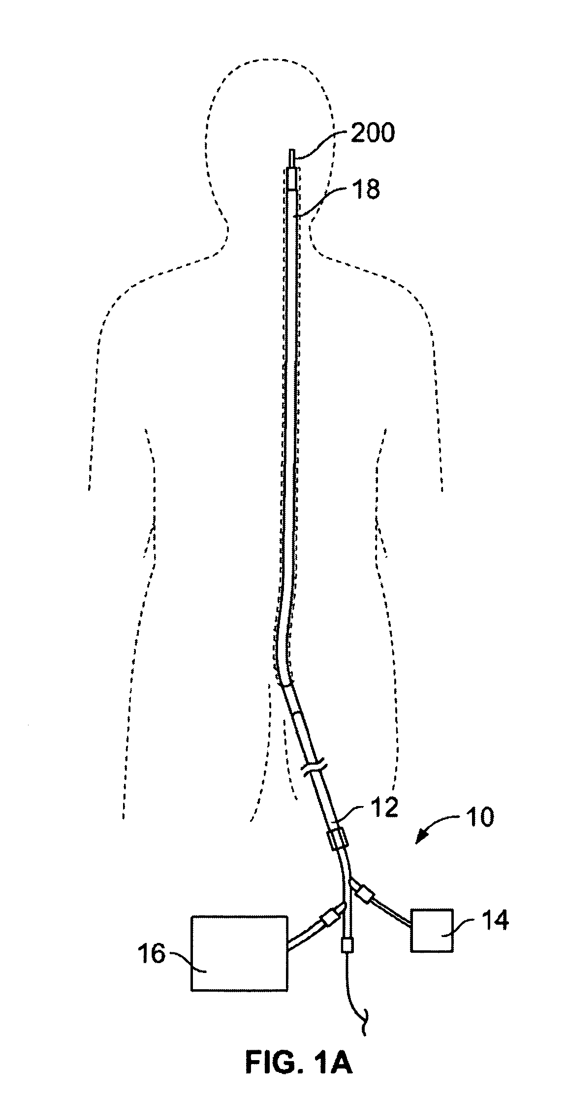
[0016]The operation of the devices and method described herein secure the obstruction, overcome the friction forces acting on the obstruction, and then remove the obstruction from the anatomy without losing or fractionating the obstruction. In one variation of the invention, this is accomplished by the obstruction removal device interacting with the obstruction in the following manner: (1) a catheter passes distal to the obstruction by passing either through the obstruction and / or between the obstruction and the vascular wall; (2) a first capturing portion is deployed distally to the obstruction and the catheter is withdrawn proximal to the obstruction; (3) the capturing portion is then translated over the obstruction by withdrawing the main bundle. Since the main bundle is affixed to a distal end of the capturing portion, misalignment between the bundle and the capturing portion does not cause distortion of the open proximal end. Since the open proximal end remains expanded against the lumen wall, the capturing portion can then be advanced over the obstruction.
[0017]The method and systems may also include the use of an additional capturing portion having an open distal end. This configuration allows the first capturing portion and second capturing portion to envelop or ensnare the obstruction from both the proximal and distal sides. Additional variations even allow for temporarily locking the two capturing portions together. Such a feature increases the ability to remove the obstruction from the body
[0019]It should be noted that in some variations of the invention, all or some of the device can be designed to increase their ability to adhere to the obstruction. For example, the wires may be coupled to an energy source (e.g., RF, ultrasonic, or thermal energy) to “weld” to the obstruction. Application of energy to the device can allow the surrounding portion to deform into the obstruction and “embed” within the obstruction. Alternatively, the device can impart a positive charge to the obstruction to partially liquefy the obstruction sufficiently to allow for easier removal. In another variation, a negative charge could be applied to further build thrombus and nest the device for better pulling force. The wires can be made stickier by use of a hydrophilic substance(s), or by chemicals that would generate a chemical bond to the surface of the obstruction. Alternatively, the filaments may reduce the temperature of the obstruction to congeal or adhere to the obstruction.
