

Brush head and method of operating the brush head
- Summary
- Abstract
- Description
- Claims
- Application Information
AI Technical Summary
Benefits of technology
Problems solved by technology
Method used
Image

Examples
Embodiment Construction
[0060]The invention and aspects / examples of it are disclosed below with reference to FIGS. 1 to 9.
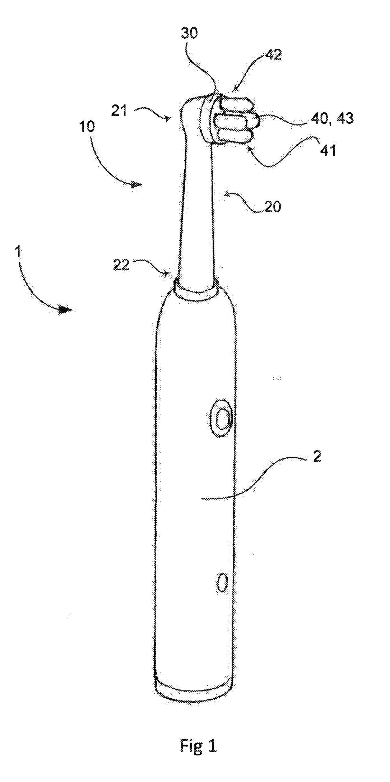
[0061]Referring to FIG. 1, the invention concerns an electrical toothbrush 1 comprising a handle 2 and a brush head 10. The brush head 10 comprises a brush head shaft 20 having an free or upper end 21 and a lower end 22 and further comprises a tuft plate 30 oscillatable about its centre axis. The lower end 22 of the brush head shaft 20 is adapted for detachable and oscillation operative connection to the handle 2 of the electric tooth brush 1. The tuft plate 30 is e.g. fixedly or non-detachably attached or detachably / releasably attached to the upper end 21 of the brush head shaft 20 for example by means of a snap-in function. The brush head 10 is for example releasably attached to the handle 2 for example by sliding or threading it thereon, e.g. by use of a bayonet mount, by clamping or held by friction or by use of a snap-in function or other similar means. The tuft plate 30 features a...
PUM
 Abstract
Description
Claims
Application Information