Device and method of applying a parity to encrypt data for protection

Inactive Publication Date: 2005-03-03
SUNPLUS TECH CO LTD
4 Cites 6 Cited by

AI-Extracted Technical Summary

Problems solved by technology

Due to the importance of intellectual properties, manufactories typically encrypt their intellectual property (IP) related data, including programs, off-line for data protection and store the data encrypted in a non-volatile memory or storage medium, such that an unauthorized person cannot restore the data even if he/she obtains the memory or storage medium with the data encrypted.
However, since the s...

Method used

[0021] The integer N can further be generated by performing a function of right rotation or left rotation. Thus, randomness of the inserting position N is increased and accordingly the inserting position cannot be obtained easily by reverse inference.
[0033] In view of foregoi...

Benefits of technology

[0007] The object of the present invention is to provide a device and method of applying a parity operation to encrypt data for protection, thereby avoiding complicated...

Abstract

A device and method of applying a parity to encrypt data for protection is disclosed. A parity generator generates a parity bit in accordance with a data to be outputted. A first parity location generator generates an inserting position N for the parity bit in accordance with a predetermined algorithm. A parity-inserting unit inserts the parity bit in a position between (N−1)th and Nth-bit of the data in accordance with the inserting position N, thereby generating an encrypted data.

Application Domain

Technology Topic

Parity bit

Image

  • Device and method of applying a parity to encrypt data for protection
  • Device and method of applying a parity to encrypt data for protection
  • Device and method of applying a parity to encrypt data for protection

Examples

  • Experimental program(1)

Example

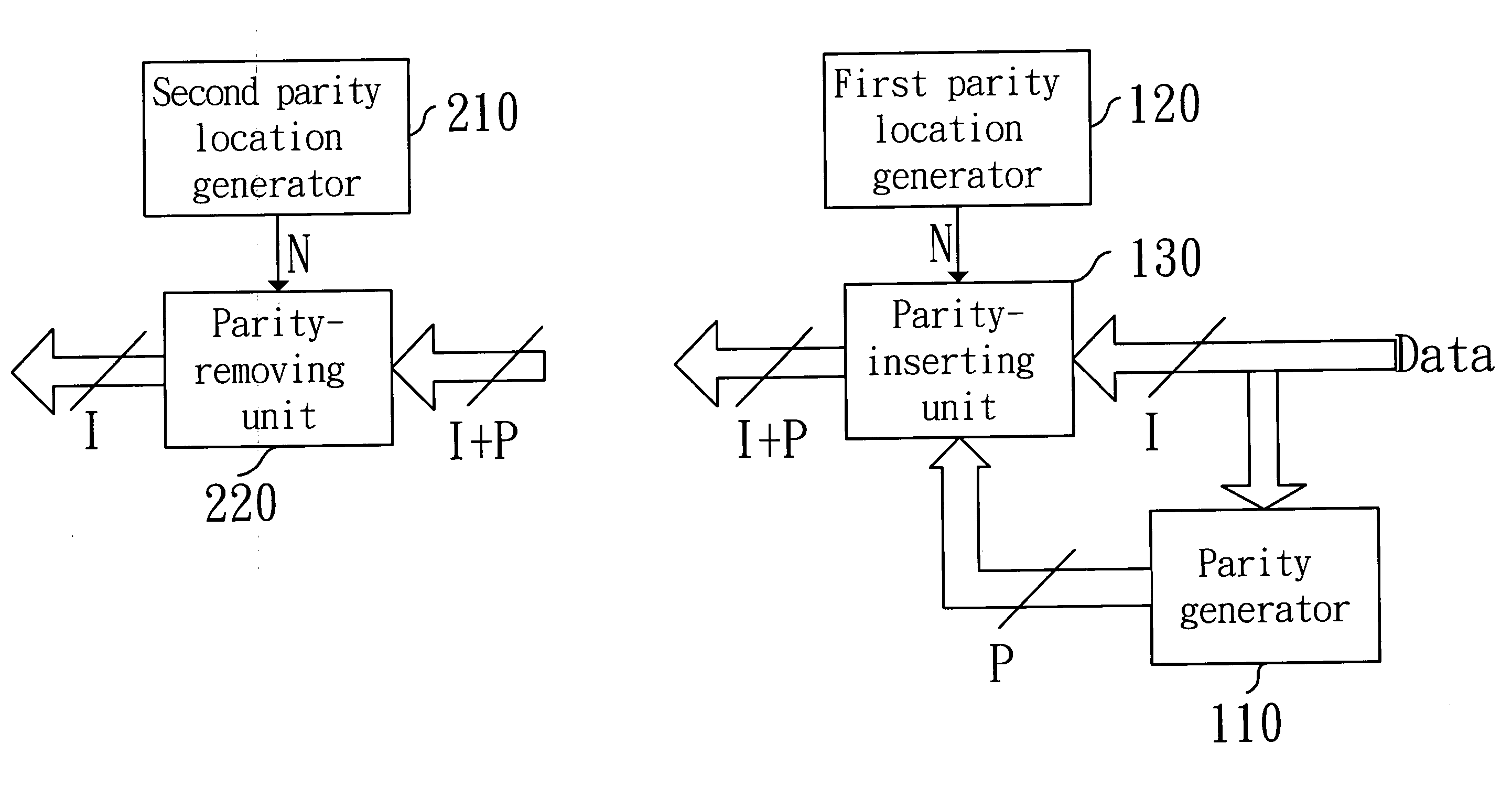
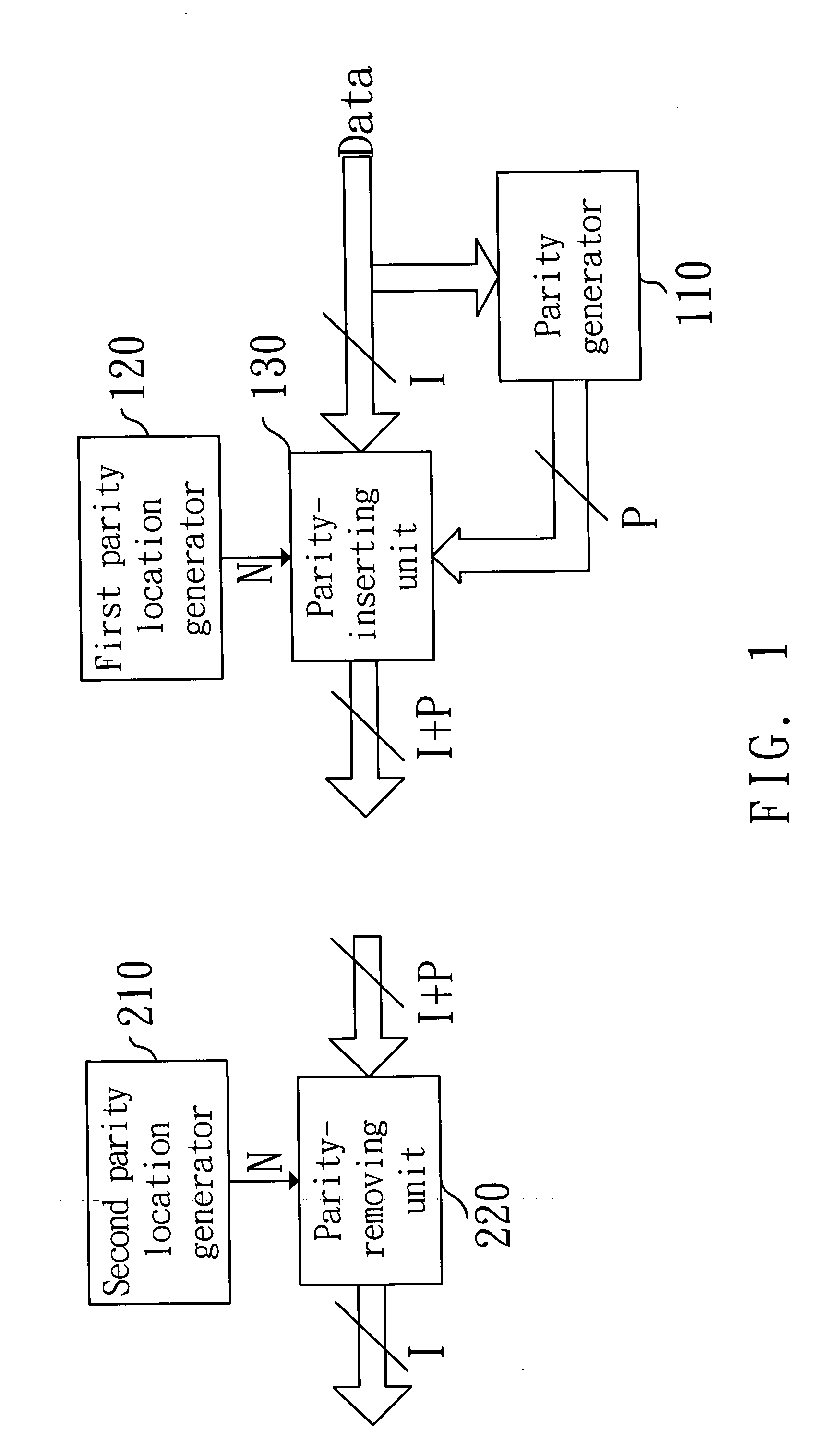
[0018]FIG. 1 is a block diagram of a device of applying a parity to encrypt data for protection in accordance with the invention. In FIG. 1, the device includes: a parity generator 110, a first parity location generator 120, a parity-inserting unit 130, a second parity location generator 210 and a parity-removing unit 220. As shown in FIG. 1, the parity generator 110, the first parity location generator 120 and the parity-inserting unit 130 encrypt data to be outputted. In addition, the second parity location generator 210 and the parity-removing unit 220 decrypt the data. The parity generator 110 generates P parity bits in accordance with I-bit data to be outputted. For simple description, 8 bits are applied for the I-bit data (I=8) and only one bit is applied for the P parity bit (P=1). The 8-bit data is processed by an XOR gate with eight input terminals and one output terminal, thus the parity is obtained.
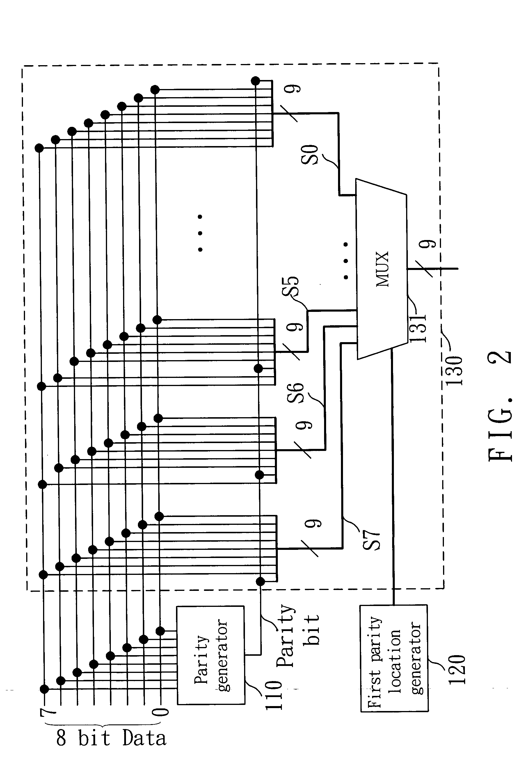
[0019] The first parity location generator 120 generates an inserting position N for the parity in accordance with a predetermined algorithm. For example, the inserting position N is obtained by computing a function of f(K) with a key, i.e., the integer N represents a position where the parity is located in the 8-bit data.
[0020] The parity-inserting unit 130 inserts the parity bit in a position between (N−1)th- and Nth-bit of the 8-bit data in accordance with the inserting position N, thereby generating a 9-bit (I+P) encrypted data.
[0021] The integer N can further be generated by performing a function of right rotation or left rotation. Thus, randomness of the inserting position N is increased and accordingly the inserting position cannot be obtained easily by reverse inference.
[0022] The second parity location generator 210 also generates the inserting position N for the parity in accordance with the predetermined algorithm. Namely, the inserting position N is obtained by computing the function of f(K) with the key, and thus the integer N represents where the parity is located in the 9-bit encrypted data. The parity-removing unit 220 receives the 9-bit encrypted data and removes the Nth bit from the 9-bit encrypted data in accordance with the inserting position N generated by the second parity location generator 210, thereby obtaining the decrypted data.
[0023]FIG. 2 is a circuit of the parity-inserting unit 130 of FIG. 1 in accordance with the invention. As shown, signal S7 is a 9-bit encrypted data after the parity bit is inserted in the 8-bit data at 8th-bit, signal S6 is a 9-bit encrypted data after the parity bit is inserted in the 8-bit data at 7th-bit, signal S5 is a 9-bit encrypted data after the parity bit is inserted in the 8-bit data at 6th-bit, and so on.
[0024] When the first parity location generator 120 generates an inserting position of 6, which represents that the parity bit is inserted between 6th- and 5th-bit of the 8-bit data, and a multiplexer 131 selects the 9-bit encrypted data at signal S5 to output. Similarly, when the first parity location generator 120 generates an inserting position of 0, which represents that the parity is inserted in 0th-bit of the 8-bit data, and the multiplexer 131 selects the 9-bit encrypted data at signal S0 to output. As such, the parity bit can be inserted in the data at any desired position.
[0025]FIG. 3 is a circuit of the parity-removing unit 220 of FIG. 1 in accordance with the invention. As shown, signal G7 is an 8-bit decrypted data after the parity bit is removed from 8th-bit of the 9-bit encrypted data, signal G6 is an 8-bit decrypted data after the parity bit is removed from 7th-bit, signal G5 is an 8-bit decrypted data after the parity bit is removed from 6th-bit, and so on.
[0026] When the second parity location generator 210 generates an inserting position with value of 8, which represents that the parity bit is inserted in 8th-bit of the 9-bit encrypted data, and a multiplexer 221 selects the 8-bit decrypted data at signal G7 to output. Similarly, when the second parity location generator 210 generates an inserting position with value of 0, which represents that the parity is inserted in 0th-bit of the 9-bit encrypted data, and the multiplexer 131 selects the 8-bit decrypted data at signal G0 to output. As such, the parity can be removed from any desired position of the encrypted data.
[0027]FIG. 4 is a block diagram of an application in accordance with the invention. In FIG. 4, an encryption system 100 has a parity generator 110, a first parity location generator 120 and a parity-inserting unit 130. A program with a plurality of bytes (8 bits each) is encrypted by the encryption system 100 to generate a 9-bit encrypted program. This encrypting procedure can be executed off-line.
[0028] In addition, an application system 200 has a second parity location generator 210, a parity-removing unit 220, a processor core 230, a parity checker 240 and a memory 250. The 9-bit encrypted program can be stored in the memory 250. Before the processor core 230 reads a program from the memory 250, the parity checker 240 first checks if the parity of the 9-bit encrypted program is right or not. When the parity of the 9-bit encrypted program is not right, an error signal is generated. When the parity of the 9-bit encrypted program is right, the parity-removing unit 220 removes the parity bit from the 9-bit encrypted program in accordance with the inserting position N generated by the second parity location generator 210, thereby obtaining a proper 8-bit program for the processor core 230.
[0029] In the present invention, the parity generator 110 is applied to generate the parity. However, other check bit generators such as Error Correcting Code (ECC) device and Cyclic Redundancy Check (CRC) device can be used.
[0030]FIG. 5 is a block diagram of another application for generating P check bits in accordance with the invention. As shown, it essentially includes a check bit generator 510, a first check bit location generator 520, a check bit inserting unit 530, a second check bit location generator 610 and a check bit removing unit 620.
[0031] As shown in FIG. 5, the check bit generator 510 generates P check bits through a check algorithm device in accordance with a data to be outputted, where P is an integer greater than or equal to 1. The check algorithm device can be an ECC device or a CRC device. The first check bit location generator 520 generates inserting positions N1, . . . , Np (an integer respectively for N, P) for the P check bits in accordance with a predetermined algorithm. The check bit inserting unit 530 inserts the P check bits respectively in a position between (Nx−1)th- and (Nx) th-bit of the data in accordance with the inserting positions N1, . . . , Np generated by the first check bit location generator 520, where x=1, . . . , P, and thus an encrypted data is generated.
[0032] The second check bit location generator 610 generates the inserting positions N1, . . . , Np for the P check bits in accordance with the predetermined algorithm. The check bit removing unit 620 receives the encrypted data and removes the P check bits from the encrypted data in accordance with the inserting positions N1, . . . , Np generated by the second check bit location generator 610. The check bits generated by such check bit generators can be used to encrypt data, without exceeding the scope of the invention.
[0033] In view of foregoing, it is known that the invention does not need to use complicated pseudo random generator and thus can save cost. In addition, hardware for generating and removing parities or check bits is very simple, which spends fewer clocks and has better performance than the prior art.
[0034] Although the present invention has been explained in relation to its preferred embodiment, it is to be understood that many other possible modifications and variations can be made without departing from the spirit and scope of the invention as hereinafter claimed.

PUM

no PUM

Description & Claims & Application Information

We can also present the details of the Description, Claims and Application information to help users get a comprehensive understanding of the technical details of the patent, such as background art, summary of invention, brief description of drawings, description of embodiments, and other original content. On the other hand, users can also determine the specific scope of protection of the technology through the list of claims; as well as understand the changes in the life cycle of the technology with the presentation of the patent timeline. Login to view more.

Similar technology patents

Device for removing or inserting a fuse

InactiveUS20050001439A1Cost savingIncrease versatilityPliersMetal-working hand toolsEngineeringProximal point
Owner:LISA DRAXLMAIER GMBH

Classification and recommendation of technical efficacy words

  • Cost saving
  • Increased access

Bluetooth-enable intelligent electronic device

ActiveUS20070096765A1Cost savingQuickly collect dataElectric devicesDynamo-electric motor metersTransceiverCollections data
Owner:ELECTRO INDSGAUGE TECH +1

Insertable Device and System For Minimal Access Procedure

InactiveUS20090012530A1Increased accessEndoscopesLaproscopesInsertion deviceProcedure Indication
Owner:THE TRUSTEES OF COLUMBIA UNIV IN THE CITY OF NEW YORK

Telephony controlled auction

InactiveUS20060173770A1Increased accessFinanceCommerceReceived spokenTelephony
Owner:TELEPHONETICS INTERACTIVE VOICE SYST
Why Eureka
Try Eureka