This helps you quickly interpret patents by identifying the three key elements:
Problems solved by technology
Method used
Benefits of technology
Benefits of technology
[0008] It is an object of the present invention to provide a removing device for electronic components that may be used in particular for fuses, and enables electronic components in very dense arrangements in difficult-to-access places, from a long distance, to be removed from or inserted in a plug-in board or a fuse-base in a fuse strip in a safe and problem-free way.
Problems solved by technology
When using the removing devices known from the prior art, a problem may arise in that, after the ends of the device have spread and the engaging sections provided at these ends have been brought into engagement with the fuse to be removed or inserted, for example with a gripping profile on the fuse, it is furthermore necessary to apply a force to the opposite end of the device in the longitudinal direction of the device in order to safely remove or insert the fuse from or into the fuse base.
A force of this type, after the device has been attached to the fuse, may cause the ends which are engaged with the fuse to spread again with the result that the engaging sections or gripping hooks provided on the device do not remain correctly in the gripping profile of the fuse.
Therefore, there is a probability of the device's gripping hooks to become detached from the fuse's gripping contour, and hence safe removal of the fuse is no longer guaranteed.
Due to the voltage applied to these components, they have to be protected from water or moisture, so that, under certain circumstances, these components are surrounded by side walls and a cover plate, and consequently only very small gaps remain between the components and the side walls protecting these components which makes access very difficult for an operator tasked with the replacement of these components.
Therefore, it is very difficult to remove and insert the components from or into the fuse-base with a conventional removing device in a safe and problem-free way.
Method used
Image
Click on the blue label to locate the original text in one second.
Reading with bidirectional positioning of images and text.
Examples
first embodiment
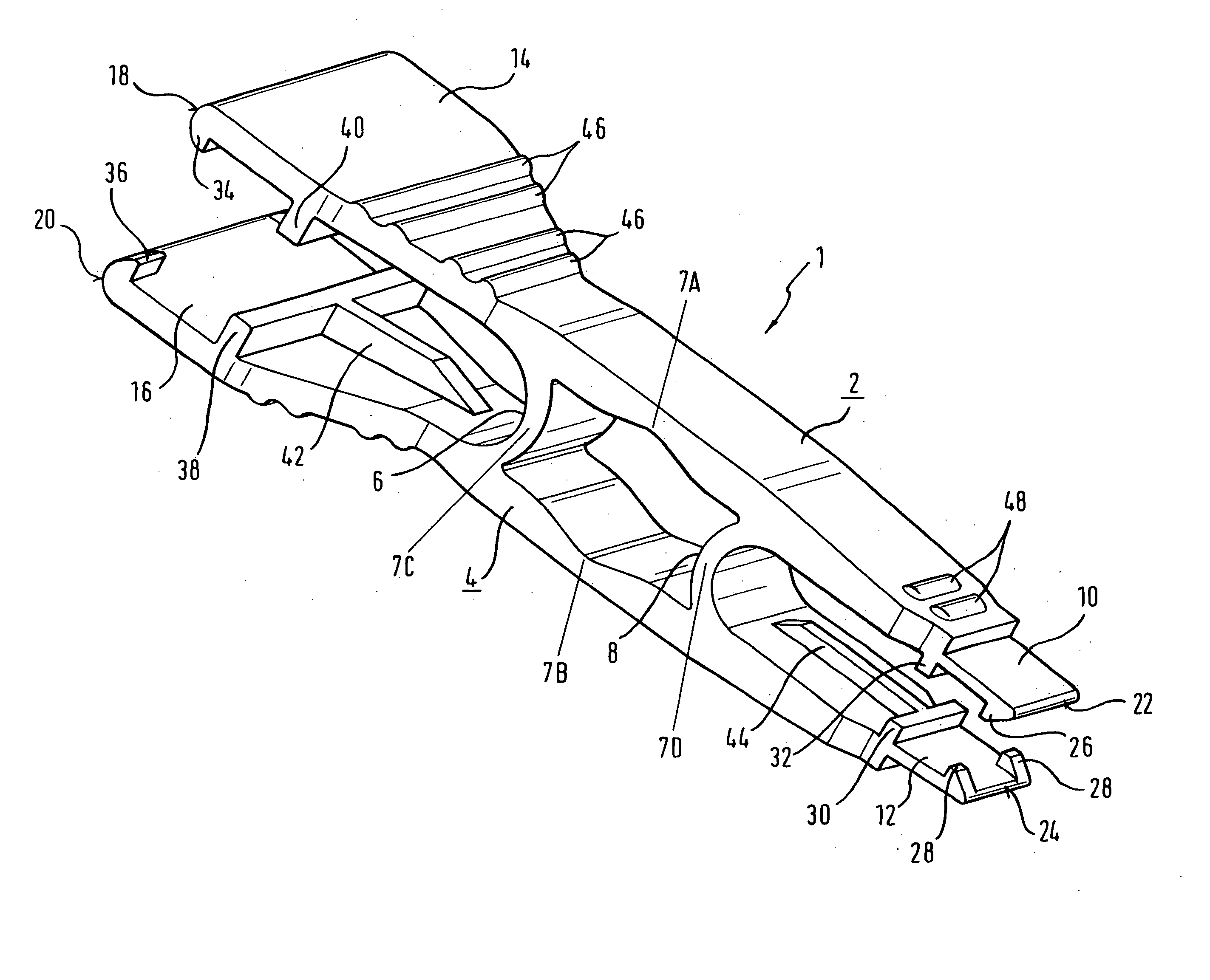
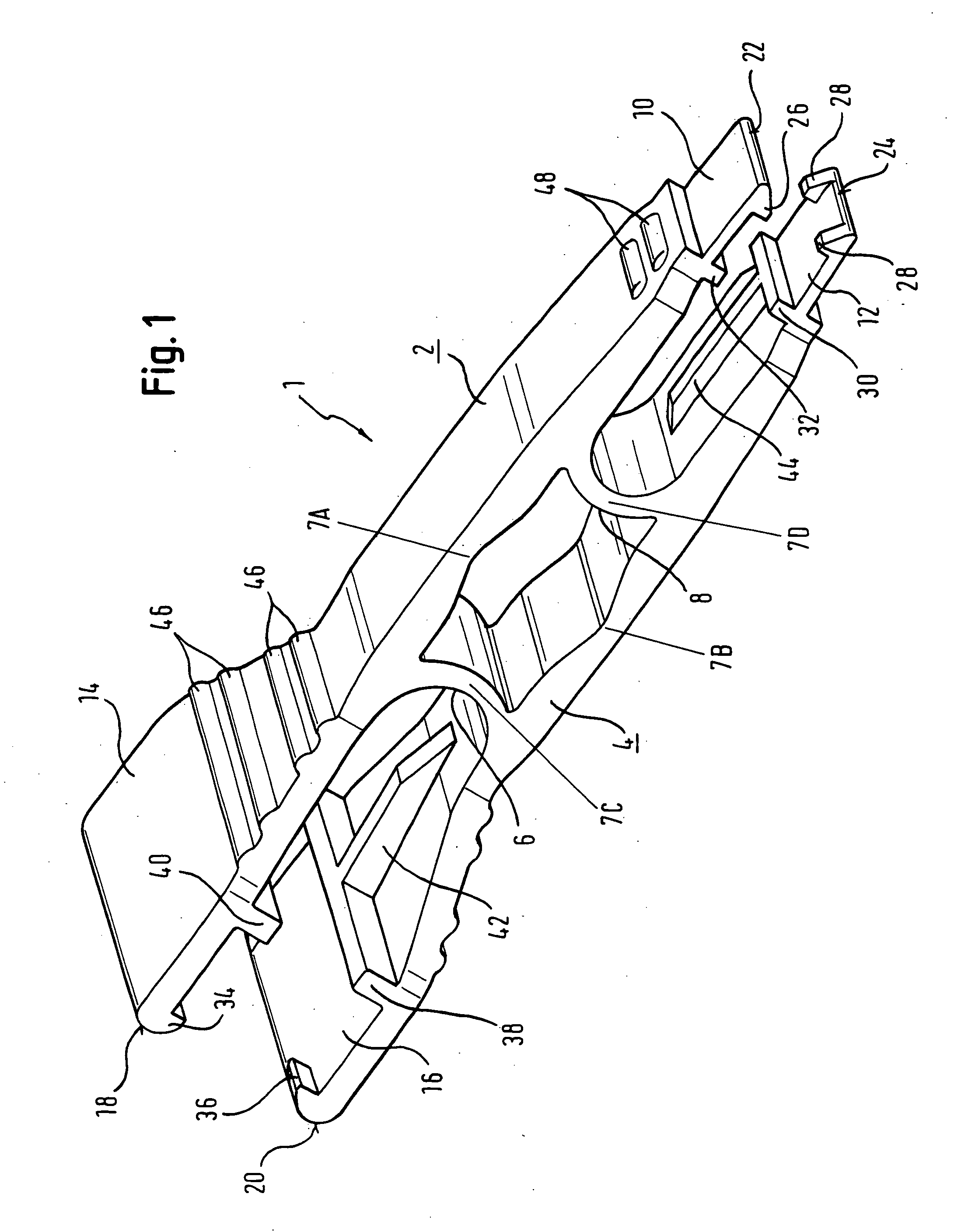
[0032]FIG. 1 is a perspective view of the removing device according to the invention. The removing device is generally indicated by reference number 1.
[0033] The device has two elongate arms 2, 4 which are substantially arranged parallel to each other. However, also conceivable are arrangements in which the arms are not arranged parallel to each other.
[0034] Arms 2, 4 are connected to each other in a central portion by two connecting sections 6, 8. The connecting sections 6, 8 of the first embodiment of the device according to the invention have a curved shape, whereby the distance of the connecting sections in the longitudinal direction of the arms is shortest in a central portion of the connecting sections. In other words, the first connecting section 8 is curved towards the left end of the device in FIG. 1, while the second connecting section 6 is curved towards the right end of the device in FIG. 1.
[0035] Outside the area of the arms 2, 4 defined by the connecting sections 6, ...
second embodiment
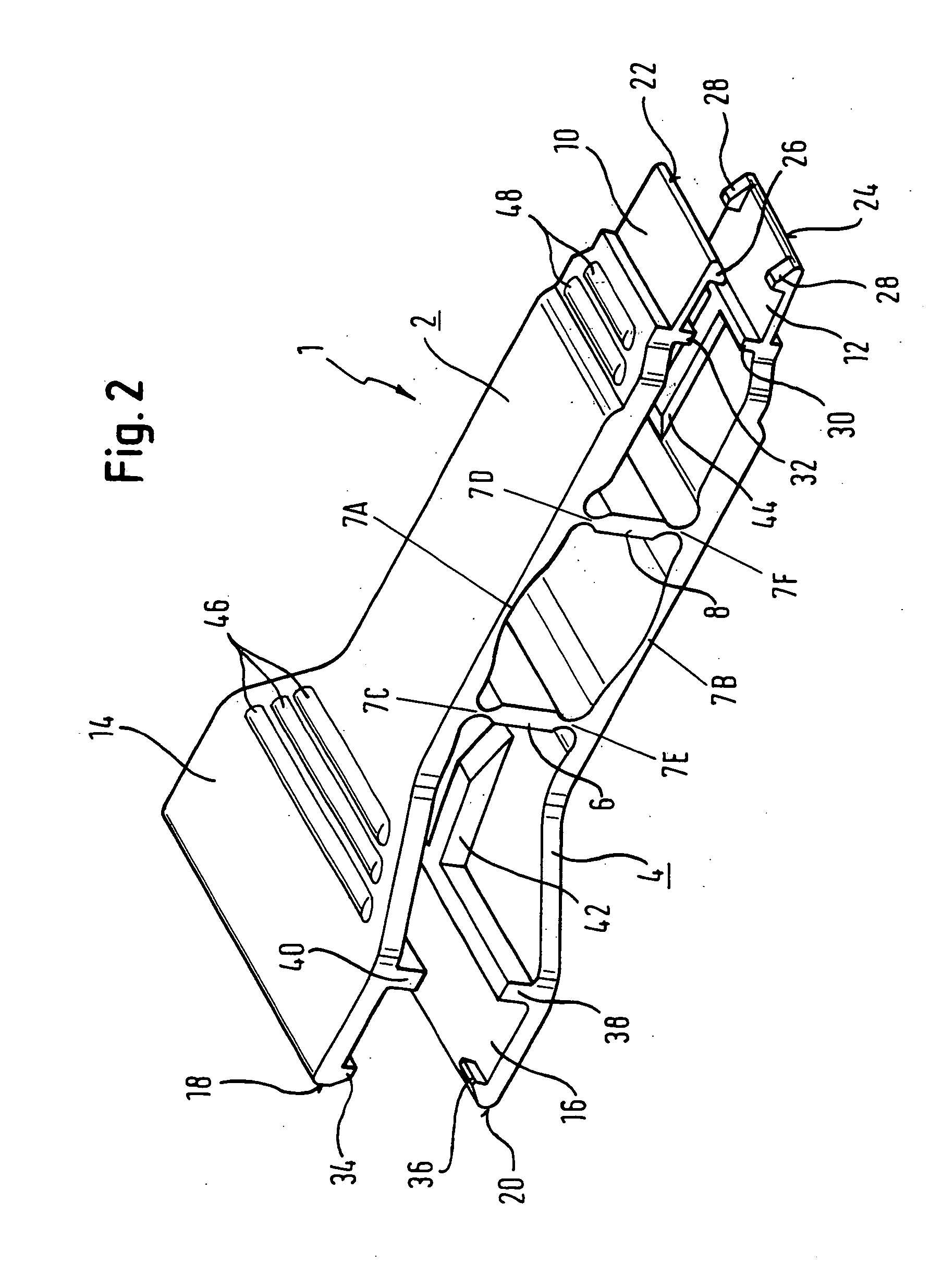
[0050]FIG. 2 shows the removing device according to the invention. However, here only those parts of this embodiment that differ from the embodiment shown in FIG. 1 will be described.
[0051] The second embodiment differs substantially from the first embodiment in the different arrangement of the articulated connections.
[0052]FIG. 2 shows six articulated connections 7A, 7B, 7C, 7D, 7E and 7F. The two articulated connections 7A, 7B hereby correspond to the articulated connections 7A, 7B identified with the same reference numbers in the first embodiment.
[0053] Due to the plate-shaped design of the connecting sections 6, 8, articulated connections 7C, 7E or 7D, 7F are arranged on their edges facing the internal surfaces of the arms 2, 4 which help to achieve the leverage. The application of a pressure force on the proximal end portion of the removing device, preferably on the portion having the ribs 46, causes the proximal half of the portion of the arms 2, 4 defined by the connecting ...
PUM
Property
Measurement
Unit
Electric charge
aaaaa
aaaaa
Current
aaaaa
aaaaa
Digital information
aaaaa
aaaaa
Abstract
The invention relates to a device for removing or inserting a fuse, in particular an automotive safety fuse from or into a fuse base in a fuse strip. The device comprises a first and a second elongate arm which each have a distal end and a proximal end whereby an engaging section that may be brought into engagement with the fuse is provided in the distal end area of the first and / or second arm and a first connecting section connecting the first and second arm to each other is provided proximally to the engaging section. The device is characterised in that a second connecting section to connect the arms at a distance is provided proximally to the first connecting section and that the first and second connecting sections and the first and second arms have articulated connections arranged in such a way that reducing the distance between the two arms in the area between the two connecting sections causes the distance between the distal ends of the two arms to increase and that reducing the distance between the two arms in the area proximal to the second connecting section cause the distance between the distal ends of the two arms to decrease.
Description
FIELD OF THE INVENTION [0001] The invention relates to a device for removing or inserting a fuse, in particular an automotive safety fuse, from or into a fuse-base in a fuse strip. The features in the preamble of claim 1 are known from DE 695 10 639 T2. PRIOR ART [0002] An extremely wide variety of devices for removing or inserting fuses of different DIN shapes from or into a fuse-base in a fuse strip is known from the prior art. [0003] For example, known from DE 695 10 639 T2 is a one-piece, plastic, injection-moulded removing device or puller with two elongate, plate-shaped arms connected by an elastic connecting section. The connecting section has a curved shape so that reducing the distance between the ends of the two arms at one end of the device causes the opposite arm ends to spread, thus bringing the claws provided on the internal surface of the arms into engagement with a fuse to be removed or inserted. The connecting section, therefore, represents an articulated connection...
Claims
Application Information
Patent Timeline
Application Date:The date an application was filed.
Publication Date:The date a patent or application was officially published.
First Publication Date:The earliest publication date of a patent with the same application number.
Issue Date:Publication date of the patent grant document.
PCT Entry Date:The Entry date of PCT National Phase.
Estimated Expiry Date:The statutory expiry date of a patent right according to the Patent Law, and it is the longest term of protection that the patent right can achieve without the termination of the patent right due to other reasons(Term extension factor has been taken into account ).
Invalid Date:Actual expiry date is based on effective date or publication date of legal transaction data of invalid patent.
IPC IPC(8): H01H85/02
CPCY10T29/53943H01H85/0208
InventorLUKASZYNSKI, TADEUSZFUSSL, PETERSALLER, ROBERT

