Systems and methods for high efficiency lighting installations

a lighting system and high-efficiency technology, applied in the field of energy-efficient lighting systems, can solve the problems of waste of valuable energy, unnecessary greenhouse emissions, and inefficient traditional lighting systems in residential and commercial locations, and achieve the effect of optimal energy saving and best user experien

Active Publication Date: 2019-01-31
WISILICA INC
View PDF3 Cites 7 Cited by
  • Summary
  • Abstract
  • Description
  • Claims
  • Application Information

AI Technical Summary

Benefits of technology

[0010]As an additional feature, each light may be equipped with dimming control built-in, such that the lighting intensity in each area of a building may be even more finely controlled to provide the optimal energy saving and best user experience.

Problems solved by technology

Traditional lighting systems in residential and commercial locations are notoriously inefficient as they are often left on when they are not needed (e.g. when the building is not occupied, or when natural daylight is available) and thus waste valuable energy while causing unnecessary greenhouse emissions.
However such sensors are often connected by wire, which means that they are fixed and thus inflexible.
Even in rare instances when lighting systems are wireless they have very limited intelligence and networking capabilities built into the system.
Such systems offer an insufficient the amount of control resulting in an unsatisfactory user experience and suboptimal energy saving.
Another limitation of many current intelligent building control systems is that their control logic is stored and executed on a central computer.
Such a configuration is problematic because it increases the cost and complexity of lighting systems when scaling the number of connecting devices and nodes to the central computer.
Therefore, due to the weakness of current lighting solutions, there is a current and impending need for lighting systems that are low energy, offer a high degree of control, and are scalable.

Method used


Image

  • Systems and methods for high efficiency lighting installations
  • Systems and methods for high efficiency lighting installations
  • Systems and methods for high efficiency lighting installations

Examples


Embodiment Construction

[0024]For the purpose of promoting an understanding of the principles of the present disclosure, reference will now be made to the embodiments illustrated in the drawings and specific language will be used to describe the same. It will, nevertheless, be understood that no limitation of the scope of the disclosure is thereby intended; any alterations and further modifications of the described or illustrated embodiments, and any further applications of the principles of the disclosure as illustrated therein are contemplated as would normally occur to one skilled in the art to which the disclosure relates. All limitations of scope should be determined in accordance with and as expressed in the claims.

Intelligent Networked Lighting System

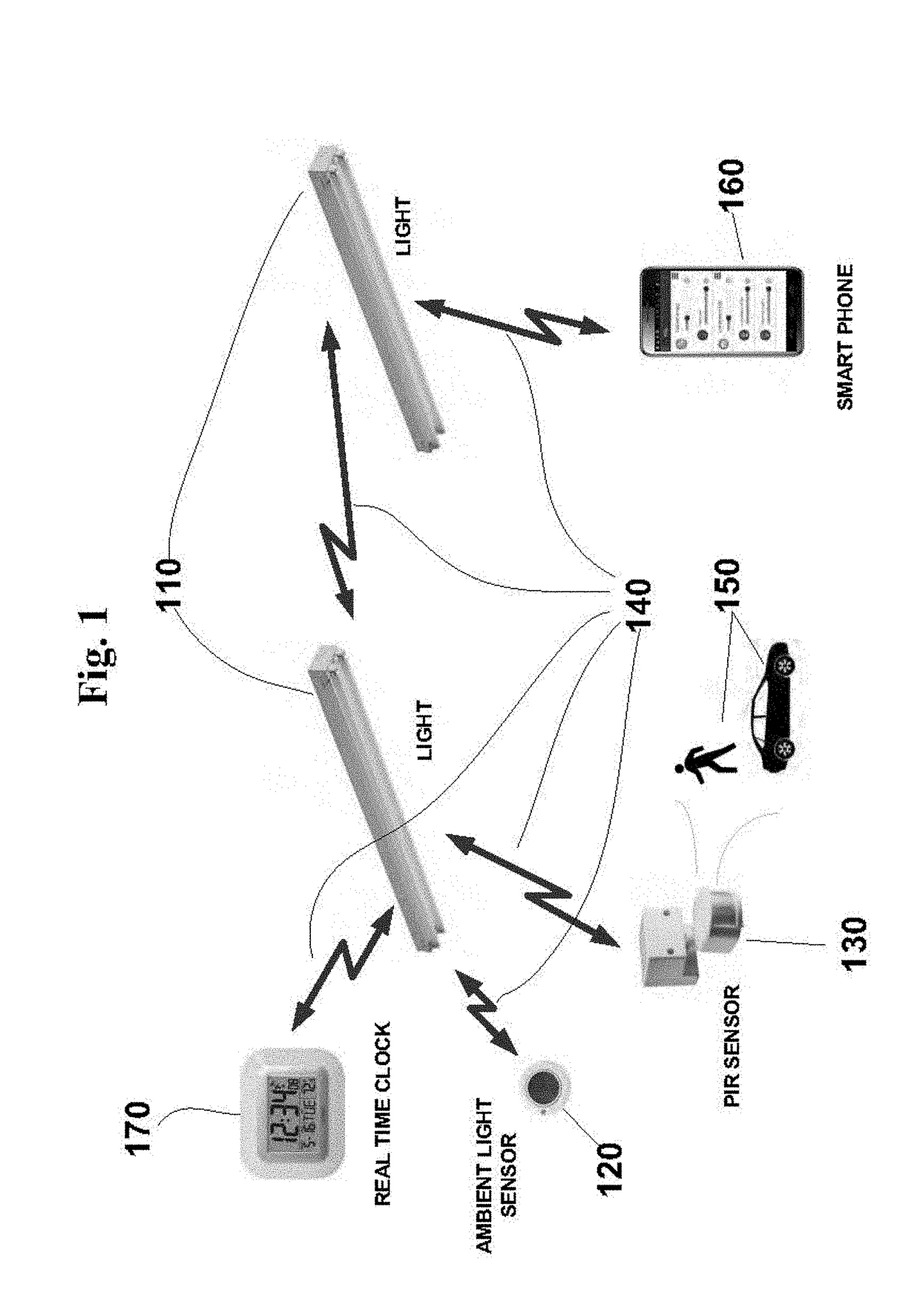
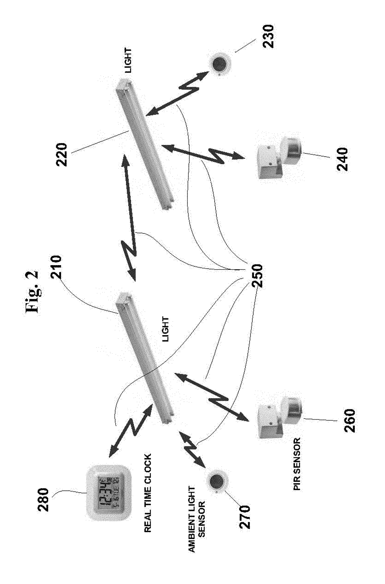
[0025]It is an objective of this disclosure to provide an intelligent lighting system whereby each light may be individually controlled by its own built-in logic and in response to events generated by other devices connected by a wireless network, to ac...


PUM


Abstract

This disclosure provides a system of intelligent lights together with control devices and sensors communicating over a wireless network, with methods to allow the lights to take actions based on logical combinations of events generated by other devices. The lights can function autonomously as they have built-in functions of logic processing, storage and wireless communications which allow them to receive events and take actions according to the stored logic configuration data. Complete freedom in the grouping of lights as well as association of control devices and sensors to each individual lights is enabled by this system architecture. Seamless communication coverage is enabled by a wireless protocol that allows the light to form a mesh network. The discovery of devices in the network and their capabilities/services, as well as the setting up of the logic configuration data for the lights, are performed by a smart phone or similarly device with user interface, which facilitates simpler hardware for the lights as well as making it easy to add new devices and discovering their capabilities/services. Additional functions of the intelligent lights are location-based services using periodic broadcast data packets transmitted from the lights, as well as receiving broadcast data packets from other devices.

Description

CROSS-REFERENCE TO RELATED APPLICATIONS[0001]This present disclosure claims the benefit of U.S. Provisional Application Ser. No. 62 / 087,161 Dec. 3, 2014, Ser. No. 62 / 100,482, filed on Jan. 7, 2015, and Ser. No. 62 / 131,842, filed on Mar. 12, 2015.TECHNICAL FIELD[0002]The present invention relates generally to the field of energy efficient lighting systems. Specifically the present invention relates to lighting systems that are connected, managed and optimized via wireless mesh networks.BRIEF BACKGROUND[0003]With the growing demands on the existing power grid—coupled with an ever-increasing threat of climate change—improving energy efficiently has become a forefront concern for many new and existing lighting system installations. Traditional lighting systems in residential and commercial locations are notoriously inefficient as they are often left on when they are not needed (e.g. when the building is not occupied, or when natural daylight is available) and thus waste valuable energy ...

Claims


Application Information

Patent Timeline
Patent Type & Authority Applications(United States)
IPC IPC(8): H04L12/28H05B37/02
CPCH04L12/282H05B37/0272H05B37/0218H05B37/0227H04L2012/2841H04W4/023H04W4/30H04W4/80H05B47/11H05B47/13H05B47/19Y02B20/40
Inventor SINGAMSETTY, SURESH KUMARKWAN, DENNIS CHING CHUNG
Owner WISILICA INC
Why Eureka
Try Eureka