Ocular Implant Systems

a technology of ocular implants and ocular nerves, applied in the field of ocular nerve implants, can solve the problems of irreversible damage to the optic nerve and loss of vision, significant changes in the iop related to the cardiac cycle, and erratic dosages, and achieve the effects of reducing the risk of ocular nerve damage, and improving the quality of li

Inactive Publication Date: 2019-02-07
ISTAR MEDICAL
View PDF0 Cites 8 Cited by
  • Summary
  • Abstract
  • Description
  • Claims
  • Application Information

AI Technical Summary

Benefits of technology

[0015]It is therefore an object of the present invention to provide an implantation device which does not require that an implant is ejected from the device.

Problems solved by technology

However, there may be significant changes in the IOP related to the cardiac cycle, blinking, diurnally and other causes.
Over time, this pressure increase results in irreversible damage to the optic nerve and loss of vision.
Erratic dosages, side effects and poor patient compliance are common issues.
Whilst devices are known for implanting stents and intraocular implants, they tend to have disadvantages, such as, the stent needs to be mounted on a guide or shaft by means of a lumen for implantation or the implant needs to be ejected from the device into the correct location within the eye as described in U.S. Pat. No. 8,852,136 and U.S. Pat. No. 8,388,568 described above.
However, in each embodiment of the implantation system described in WO-A-2011 / 084550, as the delivery controller is only attached to either the mandrel or the mandrel guide, there is no stability provided within the housing to ensure smooth and stable movement as the substance is implanted into the eye.

Method used


Image

  • Ocular Implant Systems
  • Ocular Implant Systems
  • Ocular Implant Systems

Examples


Embodiment Construction

[0067]The present invention will be described with respect to particular embodiments and with reference to certain drawings but the invention is not limited thereto. The drawings described are only schematic and are non-limiting. In the drawings, the size of some of the elements may be exaggerated and not drawn on scale for illustrative purposes.

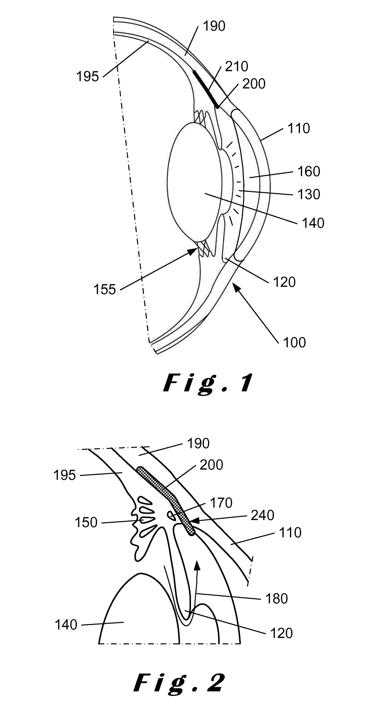
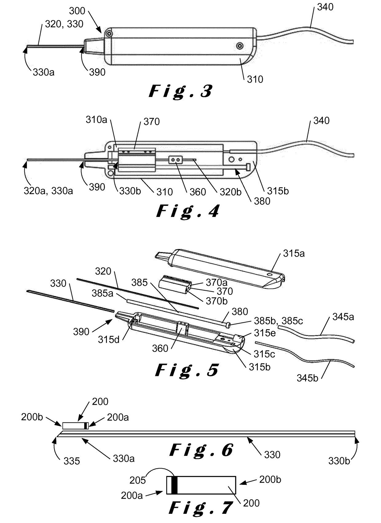
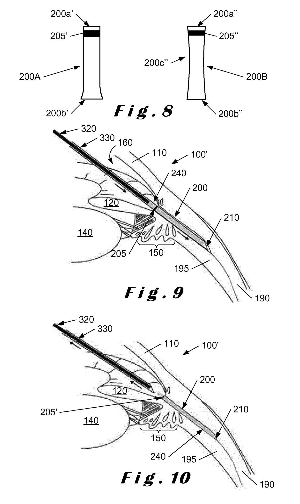
[0068]The present invention relates to a system which comprises a single-use “minimally-invasive” implantation or deployment device from which an intraocular shunt or implant is deployed into the suprachoroidal space, that is, the space lying between the sclera and the choroid of the eye, or into the subconjunctival space, that is, the space lying between the conjunctiva and the sclera of the eye. The intraocular shunt or implant is pre-loaded within a portion of the implantation or deployment device and is released therefrom as will be described in more detail below. In one embodiment, the implantation or deployment device is single use, bu...


PUM


Abstract

Described herein is an ocular implant system in which an implant (200) is deployed in a posterior space of the eye, for example, the suprachoroidal space or the subconjunctival space or the intrascleral space, with an access within the anterior chamber (160) for reducing intraocular pressure therein. The shunt (200) is implanted using an implantation device comprising a hollow shaft (330) mounted over a fixed shaft (320). The shunt (200) is located in a distal end of the hollow shaft (330) and adjacent a distal end of the fixed shaft (320), the distal end of the fixed shaft being located at a position behind the distal end of the hollow shaft. Once the distal end of the hollow shaft (330) with the shunt (200) is located at the desired depth within the posterior space, the hollow shaft is withdrawn over the fixed shaft towards the proximal end thereof to leave the shunt in the posterior space with an access within the anterior chamber (160).

Description

FIELD OF THE INVENTION[0001]The present invention relates to ocular implant systems, and is more particularly, although not exclusively, concerned with devices for delivering ocular implants to a predetermined location in the eye.BACKGROUND OF THE INVENTION[0002]The mammalian eye comprises an anterior chamber located between the cornea and the iris and lens. This chamber is filled with a fluid known as aqueous humour. A trabecular meshwork, comprising a plurality of microscopic passageways, is located in the angle between the iris and the cornea. In the normal human eye, aqueous humour is generated at a constant rate, typically about 2.2 to 2.7 microlitres per minute (μl / min), by the ciliary body behind the iris. In the conventional outflow pathway, this aqueous humour flows past between the lens and iris and then exits via the trabecular meshwork and is returned to the circulatory system.[0003]The intraocular pressure (IOP) maintaining this outflow from the normal eye tends to rema...

Claims


Application Information

Patent Timeline
Patent Type & Authority Applications(United States)
IPC IPC(8): A61F9/007A61B90/00
CPCA61F9/00781A61B90/39A61F2230/0069A61F2230/0008A61F2250/0097A61F2210/0071A61B2090/3941A61F9/0017A61B17/3468
Inventor VANDIEST, NICOLASDE MARCO, EMILIANOROY, CECILE
Owner ISTAR MEDICAL
Why Eureka
Try Eureka