Seal sacrificial wear indicator

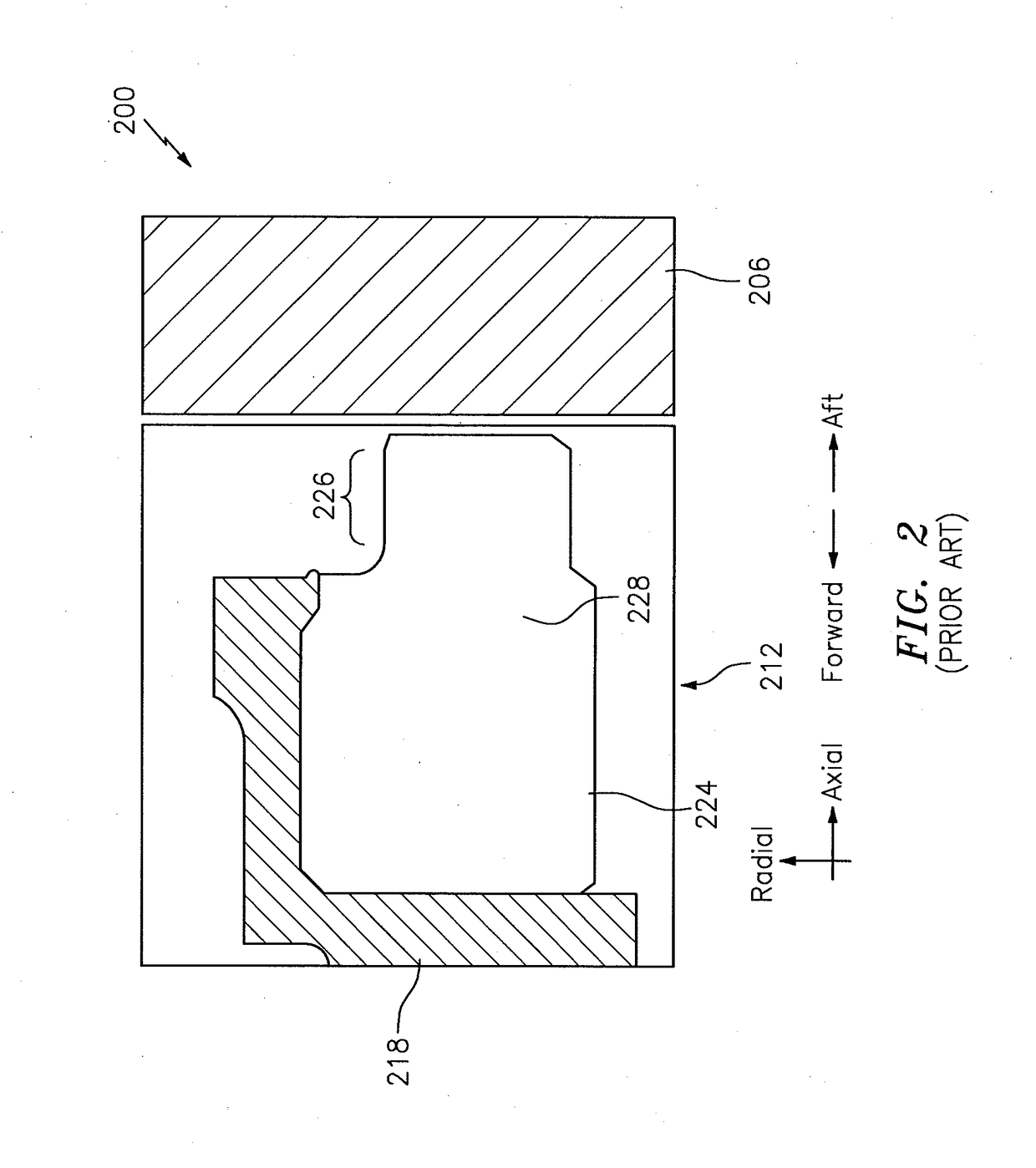
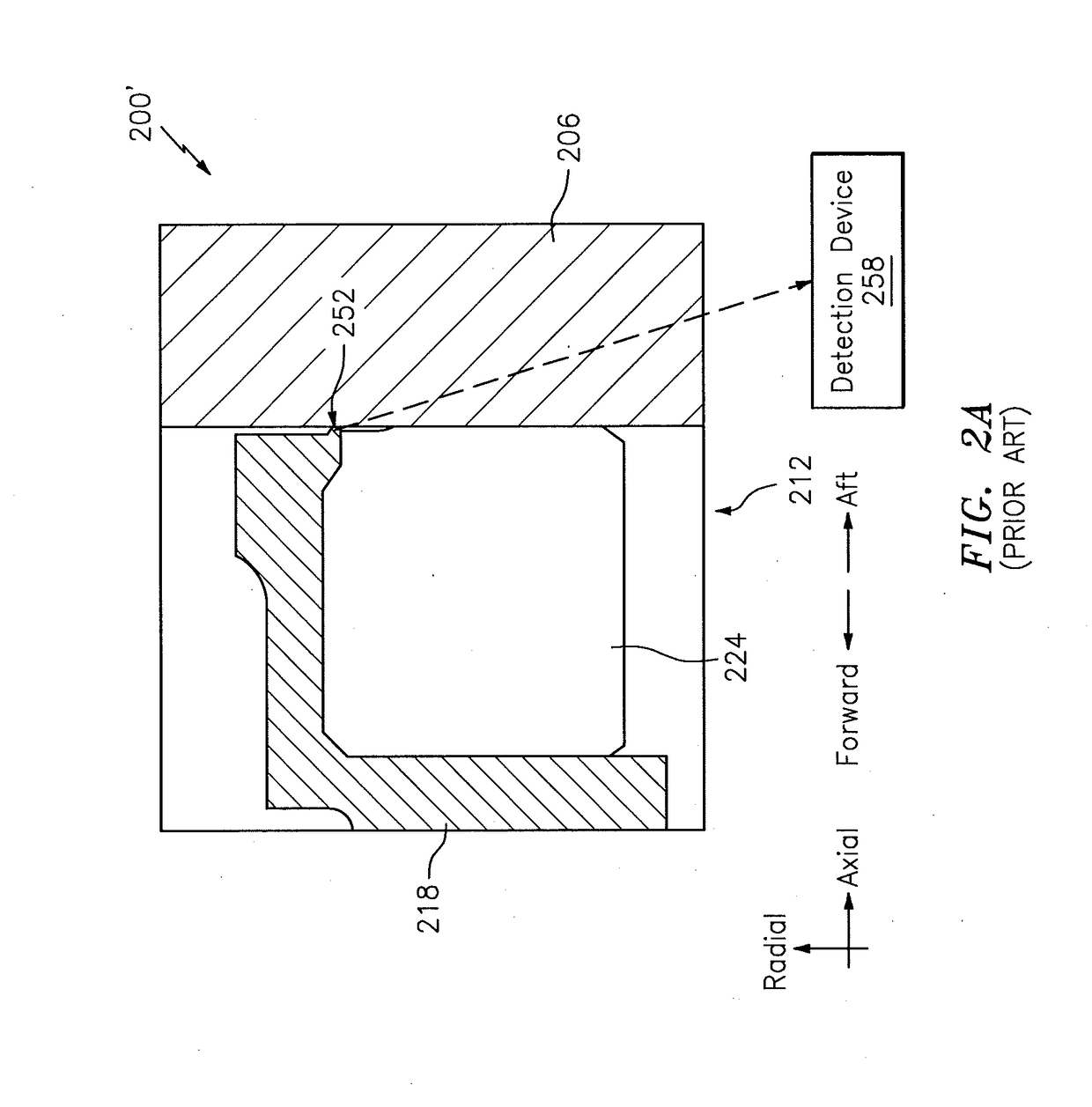
a technology of wear indicator and seal, applied in the direction of leakage prevention, mechanical equipment, machines/engines, etc., can solve the problems of significant wear of the nose b>226/b>, excessive wear, and replacement activity a significant cost in terms of engine removal from servi

Active Publication Date: 2019-02-07
RTX CORP
View PDF22 Cites 10 Cited by
  • Summary
  • Abstract
  • Description
  • Claims
  • Application Information

AI Technical Summary

Benefits of technology

[0008]The following presents a simplified summary in order to provide a basic understanding of some aspects of the disclosure. The summary is not an extensive overview of the disclosure. It is neither intended to identify key or critical elements of the disclosure nor to delineate the scope of the disclosure. The following summary merely presents some concepts of the disclosure in a simplified form as a prelude to the description below.
[0009]Aspects of the disclosure are directed to a system comprising: a rotatable seal runner, a stationary sealing member that includes a base and a nose that extends from the base in an axial direction and interfaces with the seal runner, a carrier that supports the sealing member, and a tab coupled to the carrier, where the tab extends from the carrier in the axial direction towards the seal runner. In some embodiments, when a portion of the nose is worn the tab contacts the seal runner. In some embodiments, the portion of the nose is less than an entirety of the nose. In some embodiments, the portion corresponds to between 80% and 90% of an entirety of an axial length of the nose. In some embodiments, the system further comprises a sensor that detects and indicates when a portion of the tab is liberated from a remainder of the tab in an amount that is greater than a threshold. In some embodiments, the sensor detects when the portion of the tab is liberated from the remainder of the tab based on a material of the tab. In some embodiments, the material of the tab includes at least one of iron or nickel. In some embodiments, the tab includes a first material and the carrier includes a second material. In some embodiments, the first material is different fro...

Problems solved by technology

However, in some instances the nose 226 may incur excessive wear, such that the nose 226 may be substantially completely worn prior to a next scheduled engine maintenan...

Method used


Image

  • Seal sacrificial wear indicator
  • Seal sacrificial wear indicator
  • Seal sacrificial wear indicator

Examples


Embodiment Construction

[0018]It is noted that various connections are set forth between elements in the following description and in the drawings (the contents of which are included in this disclosure by way of reference). It is noted that these connections are general and, unless specified otherwise, may be direct or indirect and that this specification is not intended to be limiting in this respect. A coupling between two or more entities may refer to a direct connection or an indirect connection. An indirect connection may incorporate one or more intervening entities.

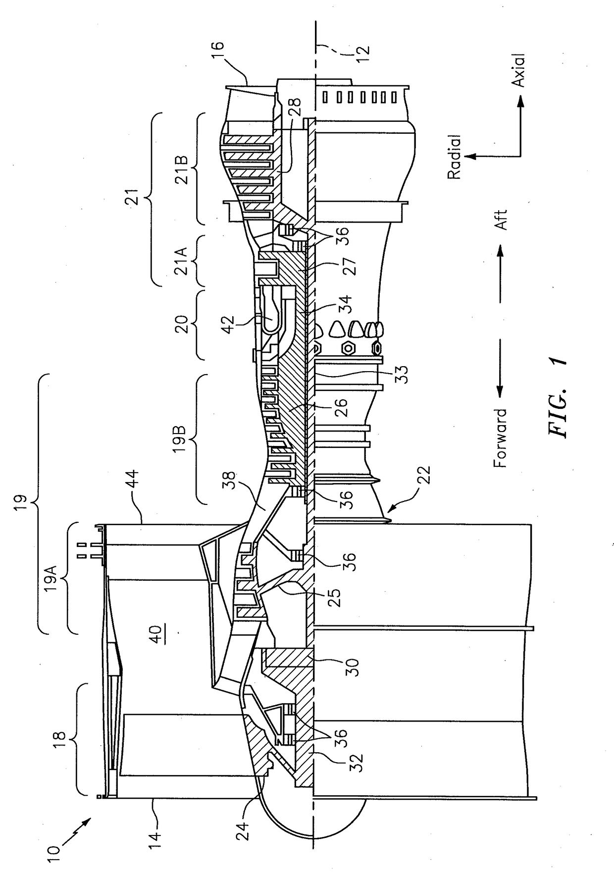
[0019]In accordance with various aspects of the disclosure, apparatuses, systems and methods are described for detecting when a sealing member has worn in an amount greater than a threshold. In some embodiments, a carrier of the sealing member may include a tab that may project towards a rotating structure. At least a portion of the tab, which may serve as a sacrificial wear member, may be collected and detected by a detection device. This...


PUM

PropertyMeasurementUnit
Fractionaaaaaaaaaa
Fractionaaaaaaaaaa
Lengthaaaaaaaaaa

Abstract

Aspects of the disclosure are directed to a system comprising: a rotatable seal runner, a stationary sealing member that includes a base and a nose that extends from the base in an axial direction and interfaces with the seal runner, a carrier that supports the sealing member, and a tab coupled to the carrier, where the tab extends from the carrier in the axial direction towards the seal runner.

Description

BACKGROUND[0001]Gas turbine engines, such as those which power aircraft and industrial equipment, employ a compressor to compress air that is drawn into the engine and a turbine to capture energy associated with the combustion of a fuel-air mixture. An engine frequently includes one or more seals. Seals are used to isolate one or more regions of the engine. Seals help to ensure stable and efficient operation of the engine.[0002]Referring to FIG. 2, a sealing system 200 is shown. The system 200 interfaces rotating structure 206 and static structure 212 in forming the seal. The rotating structure 206 is frequently referred to, or may include, a rotatable seal land / runner. As the details of the rotating structure 206 are known to one skilled in the art, a further description of the rotating structure 206 is omitted herein for the sake of brevity.[0003]The static structure 212 includes a carrier 218 and a sealing member 224. The sealing member 224 is frequently implemented as one or mor...

Claims


Application Information

Patent Timeline
IPC IPC(8): F16J15/34
CPCF16J15/3492G01M13/005F05D2300/11F01D21/003F05D2220/32F01D11/003F01D21/10F16D66/02F05D2260/80
Inventor SOMMERS, MARK T.
Owner RTX CORP
Why Eureka
Try Eureka