Gas meter
- Summary
- Abstract
- Description
- Claims
- Application Information
AI Technical Summary
Benefits of technology
Problems solved by technology
Method used
Image
Examples
first embodiment
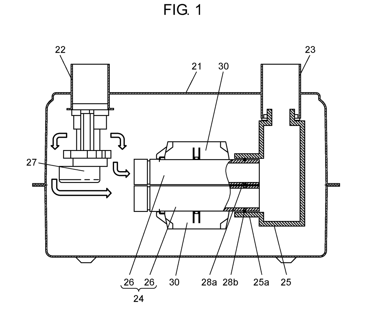
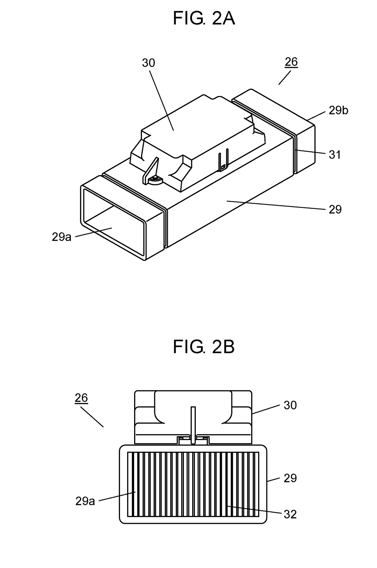
[0028]FIG. 1 is a schematic sectional view of the gas meter. As illustrated in FIG. 1, gas meter 21 is configured with meter entrance 22, meter exit 23, flow rate measurer 24, and connecting member 25. Flow rate measurer 24 is configured such that back faces (faces on a side opposite to faces on which sensor portions 30 to be described later are disposed) of two flow rate measuring units 26 are integrally bonded together as bonding faces. Connecting member 25 is provided with mounting portion 25a, and is configured such that an exit of flow rate measurer 24 can be inserted and held.
[0029]In addition, in order to secure a seal between meter exit 23 and flow rate measurer 24, that is, in order to make sure that a gas, which does not pass through flow rate measurer 24, does not flow into connecting member 25, seal member 28a is provided between two flow rate measuring units 26, and seal member 28b is provided between an outer periphery of the flow rate measurer and an inside of mountin...
second embodiment
[0060]FIGS. 8A and 8B are perspective views of a flow rate measuring unit according to a second embodiment of the disclosure. In FIGS. 8A and 8B, engaging portions 38a to 38d and engaged portions 37a to 37d, which allow flow rate measuring units 26a to be engaged with each other, are included in a lower face and side faces of each of flow rate measuring units 26a.
[0061]Engaging portions 38a to 38d are formed as protruding rectangular parallelepiped projections, engaged portions 37a to 37d are formed as sunken recessions that can be engaged with projections, which are engaging portions 38a to 38d, and the engaging portions and the engaged portions are alternately disposed as illustrated in FIGS. 8A and 8B.
[0062]Since engaging portions 38a to 38d and engaged portions 37a to 37d are disposed in this manner, it is possible to configure the joining of the flow rate measuring units illustrated in FIGS. 4 to 7 by using one type of flow rate measuring unit 26a.
[0063]As described above, ac...
PUM
 Abstract
Description
Claims
Application Information
 - R&D
- Intellectual Property
- Life Sciences
- Materials
- Tech Scout
- Unparalleled Data Quality
- Higher Quality Content
- 60% Fewer Hallucinations
Browse by: Latest US Patents, China's latest patents, Technical Efficacy Thesaurus, Application Domain, Technology Topic, Popular Technical Reports.
© 2025 PatSnap. All rights reserved.Legal|Privacy policy|Modern Slavery Act Transparency Statement|Sitemap|About US| Contact US: help@patsnap.com


