Vehicle headlamp

Inactive Publication Date: 2005-03-24
KOITO MFG CO LTD
View PDF1 Cites 4 Cited by
  • Summary
  • Abstract
  • Description
  • Claims
  • Application Information

AI Technical Summary

Benefits of technology

[0016] As indicated by the formation above, the vehicle headlamp according to the invention is formed as a projector type vehicle headlamp having the shade. However, it is feasible to make the vehicle headlamp compact by decreasing the longitudinal length of the lighting device since the light source bulb is inserted into the reflector from the lateral side of the optical axis extended in the longitudinal direction of the vehicle.
[0017] Further, the vehicle headlamp according to the invention is provided with the first additional reflector between the light source bulb and the shade, which reflector is used for reflecting light from the light source toward the area in front in the direction of inserting the bulb on the reflective surface of the reflector. Moreover, the area in front in the direction of inserting the bulb on the reflective surface of the reflector is formed as the second additional reflector for reflecting the light reflected from the first additional reflector forward and closer to the optical axis and direct light from the light source which is to be shielded by the shade is caused to be incident on the projection lens by using the first and second additional reflectors, whereby the direct light can effecti

Problems solved by technology

However, as described in JP-U-02-047704, since many light source bulbs are formed to have line light sources extended in the axial direction of the bulbs, the following problems develop when the side-inserted type lighting device is employed.
Consequently, when the side-inserted type lighting device is employed, the problem is that as the quantity of light incident on an area in the forward direction in which the bulb is inserted on the reflective surface of the reflector becomes extremely small, it i

Method used


Image

  • Vehicle headlamp
  • Vehicle headlamp
  • Vehicle headlamp

Examples


Example

[0033] An embodiment of the invention will now be described by reference to the drawings.

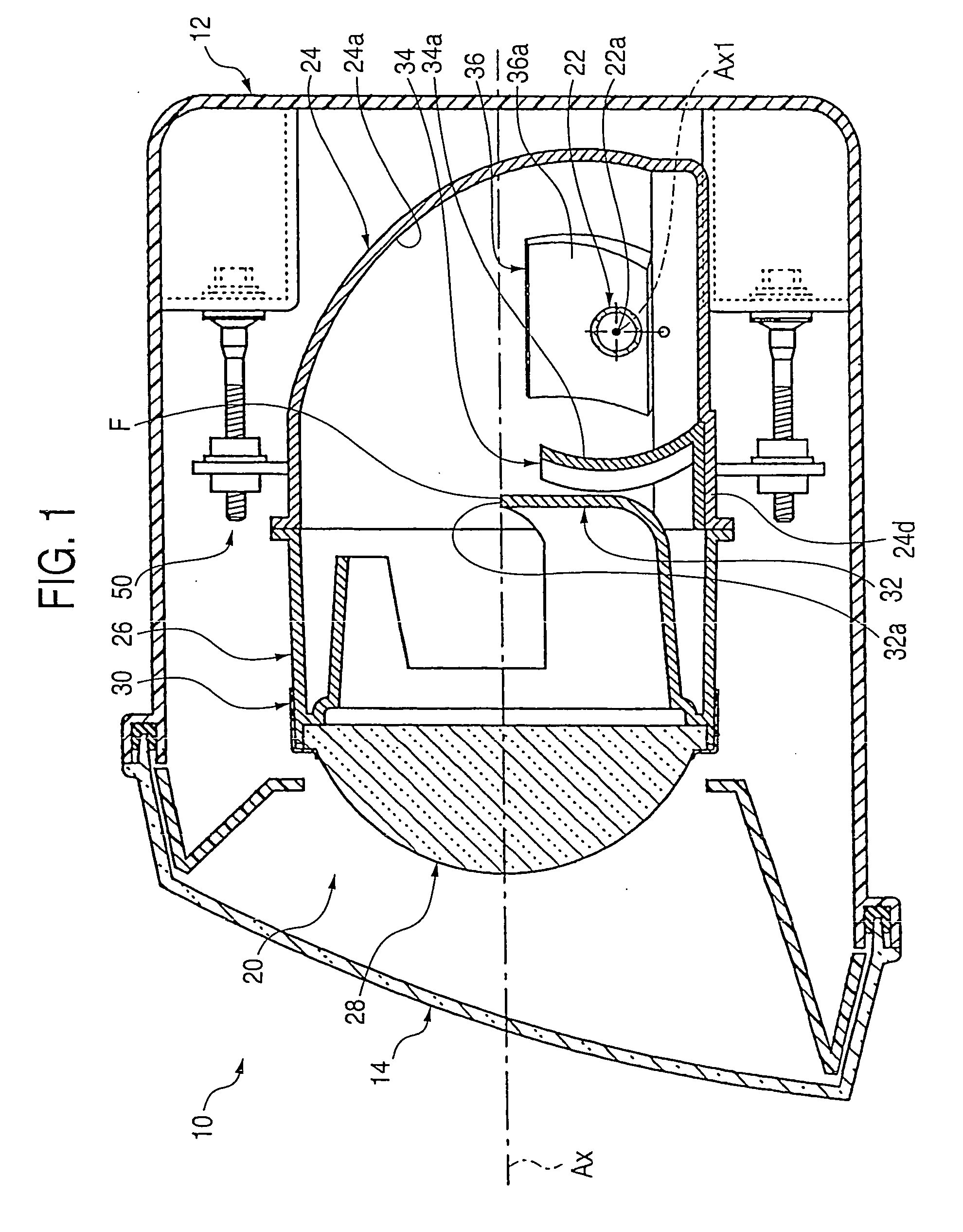
[0034]FIG. 1 is a sectional side view of a vehicle headlamp embodying the invention.

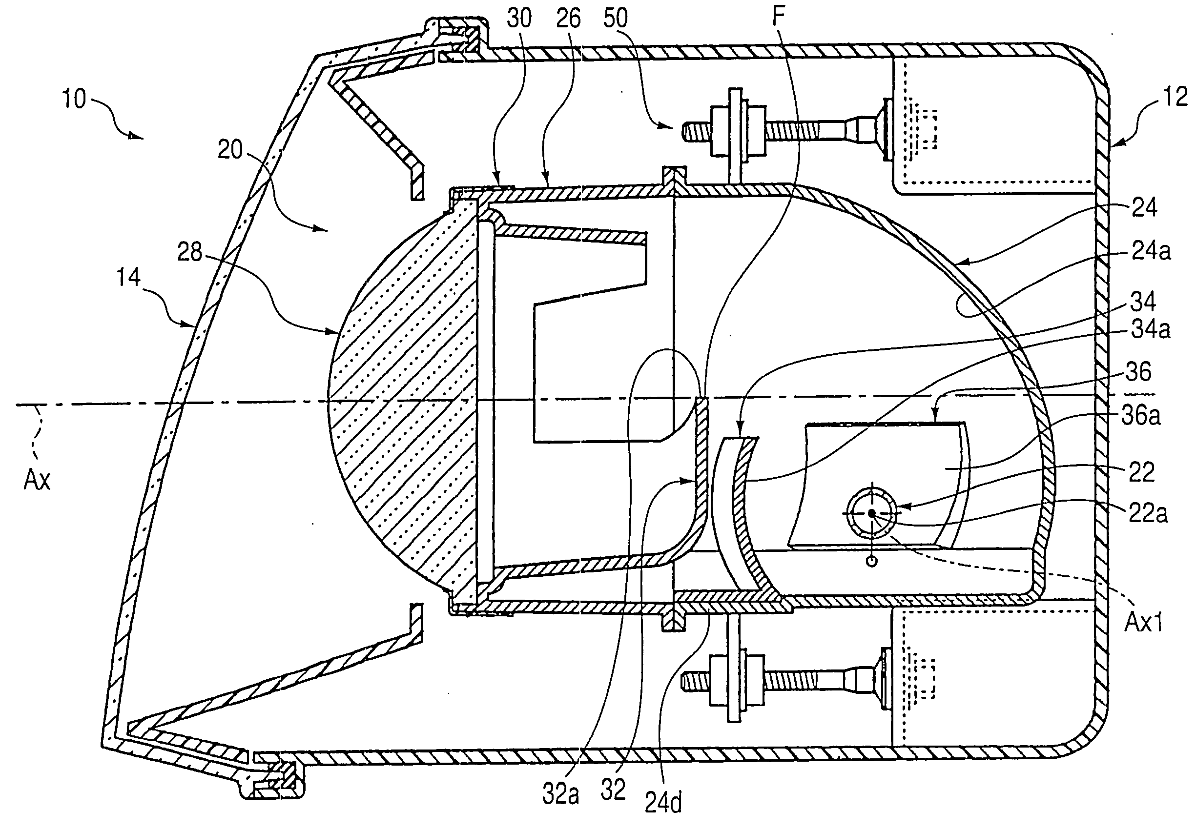
[0035] As shown in FIG. 1, a vehicle headlamp 10 embodying the invention is disposed in the right front end portion of a vehicle. A lighting device unit 20 having an optical axis Ax extending in the longitudinal direction of the vehicle is housed in a lamp chamber. The lamp chamber includes a lamp body 12 and a transparent light-permeable cover 14 mounted to a front end opening of the lamp chamber. The lighting device unit 20 is tiltable in vertical and horizontal directions via an aiming mechanism 50.

[0036] Upon completion of aiming adjustment made by the aiming mechanism 50, the optical axis Ax of the lighting device unit 20 is extended downward by approximately 0.5-0.6° with respect to the longitudinal direction of the vehicle.

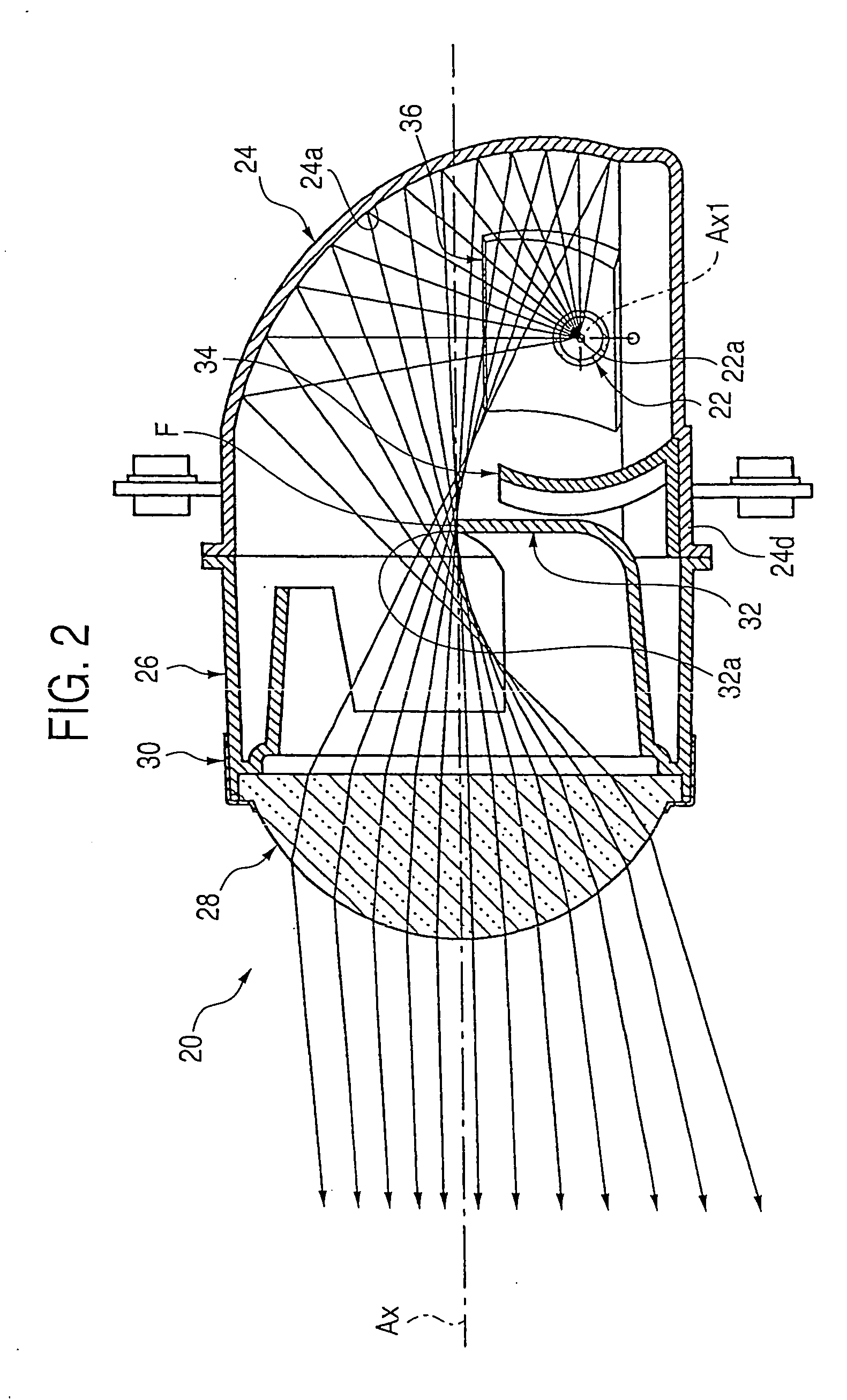
[0037]FIGS. 2 and 3 are sectional side views of the single lighting device unit ...


PUM


Abstract

A first additional reflector 34 is provided between a light source bulb 22 and a shade 32 and used for reflecting light from a light source 22a to an area in front in the direction of inserting the bulb on the reflective surface 24a of a reflector 24. Further, the area in front in the direction of inserting the bulb on the reflective surface 24a of the reflector 24 is formed as a second additional reflector 36 for reflecting the light reflected from the first additional reflector 34 forward and closer to an optical axis Ax. Thus, direct light from the light source 22a which is to be shielded by the shade 32 is caused to be incident on a projection lens 28 by using the first and second additional reflectors 34 and 36, whereby the direct light can effectively be utilized as forward irradiation light.

Description

[0001] The present application claims foreign priority based on Japanese Patent Application Nos. P.2003-331904, filed Sep. 24, 2003, the contents of which are incorporated herein by reference. BACKGROUND OF THE INVENTION [0002] The present invention relates to a so-called projector type vehicle headlamp, and more particularly, the invention relates to a vehicle headlamp so configured as to form a low-beam luminous distribution pattern. [0003] A projector type vehicle headlamp is normally equipped with a projection lens arranged on an optical axis extending in the longitudinal direction of a vehicle and a light source disposed behind the rear-side focal point, so that light from the light source is reflected by a reflector toward the optical axis. [0004] In JP-U-02-047704, a so-called side-inserted type lighting device is described with reference to a projector type vehicle headlamp of the sort mentioned above, the lighting device being configured such that a light source bulb is fix...

Claims


Application Information

Patent Timeline
IPC IPC(8): F21S8/10F21S8/12F21V7/00F21V13/00F21W101/10F21W107/10F21Y101/00
CPCF21S48/1388F21S48/119F21S41/162F21S41/255F21S41/321F21S41/43F21S41/365F21S41/172F21S41/173
Inventor YAMAMURA, SATOSHINAGANAWA, MASAHITO
Owner KOITO MFG CO LTD
Why Eureka
Try Eureka