Snorkeling tube structure and method of manufacturing the same

Inactive Publication Date: 2019-02-21
QBAS CO LTD
View PDF9 Cites 0 Cited by
  • Summary
  • Abstract
  • Description
  • Claims
  • Application Information

AI Technical Summary

Benefits of technology

The present invention provides a snorkeling tube structure with an intake and outtake passage separated from each other, and a method of manufacturing the same. The tube body has an inner surface that encircles the axis to define an air passage, and a partition portion formed integrally with the tube body to divide the air passage into an intake and outtake passage. The tube body or partition portion has a thickness not greater than 3.0 millimeters. The axis of the snorkeling tube structure comprises two end points between which a straight distance is defined. The tube body has a section surface which connects to the outer and inner surfaces, and the shape of the section surface can be a heart, water drop, star, plum blossom or triangle. The method of manufacturing the snorkeling tube structure involves forming a parison with two passages separated from each other, placing the parison in a mold and injecting air into the passages to inflate them, and then removing the inflated parison from the mold to get the snorkeling tube structure. The parison can be formed by extruding or injecting plastic material into a mold. The technical effects of the invention are a snorkeling tube structure with a suitable shape, size, and strength, and a method of manufacturing it that allows for precise control over the air passages.

Problems solved by technology

However, the user will inevitably inhale the carbon dioxide exhaled by himself / herself when the user breathes through such a snorkeling tube, thereby lowering the oxygen content in the air inhaled by the user.
Therefore, the user is likely to feel dizzy or feel the need to rise to the surface of the water frequently so that the user cannot do the snorkeling or diving sport for a long time.
Although manufacturers have attempted to develop a snorkeling tube with an intake passage and an outtake passage separated from each other, the snorkeling tube cannot meet the users' requirements due to limitations in the injection molding process.

Method used


Image

  • Snorkeling tube structure and method of manufacturing the same
  • Snorkeling tube structure and method of manufacturing the same
  • Snorkeling tube structure and method of manufacturing the same

Examples


Embodiment Construction

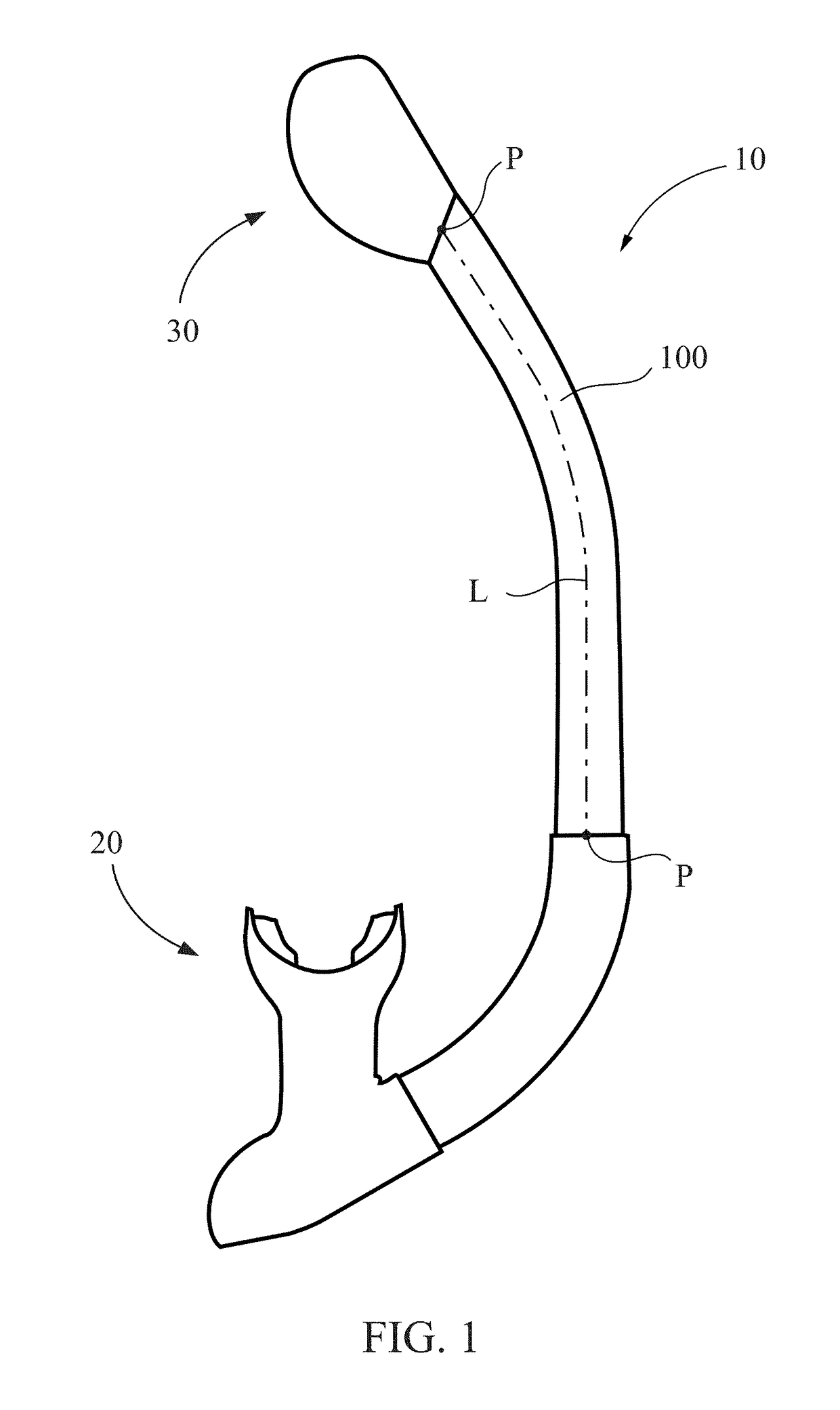
[0029]FIG. 1 illustrates a schematic view of a snorkeling tube structure 10 according to the preferred embodiment of the present invention. The snorkeling tube structure 10 may be used in a snorkel (as a constitute element of the snorkel), and may be connected to elements such as a mouthpiece assembly 20 and a waterproof member 30 of the snorkel. The snorkeling tube structure 10 may also be used in a goggle mask (not shown) with an overall mask, e.g., a goggle mask structure disclosed in a Taiwan patent application No. 106116199 applied by the applicant.

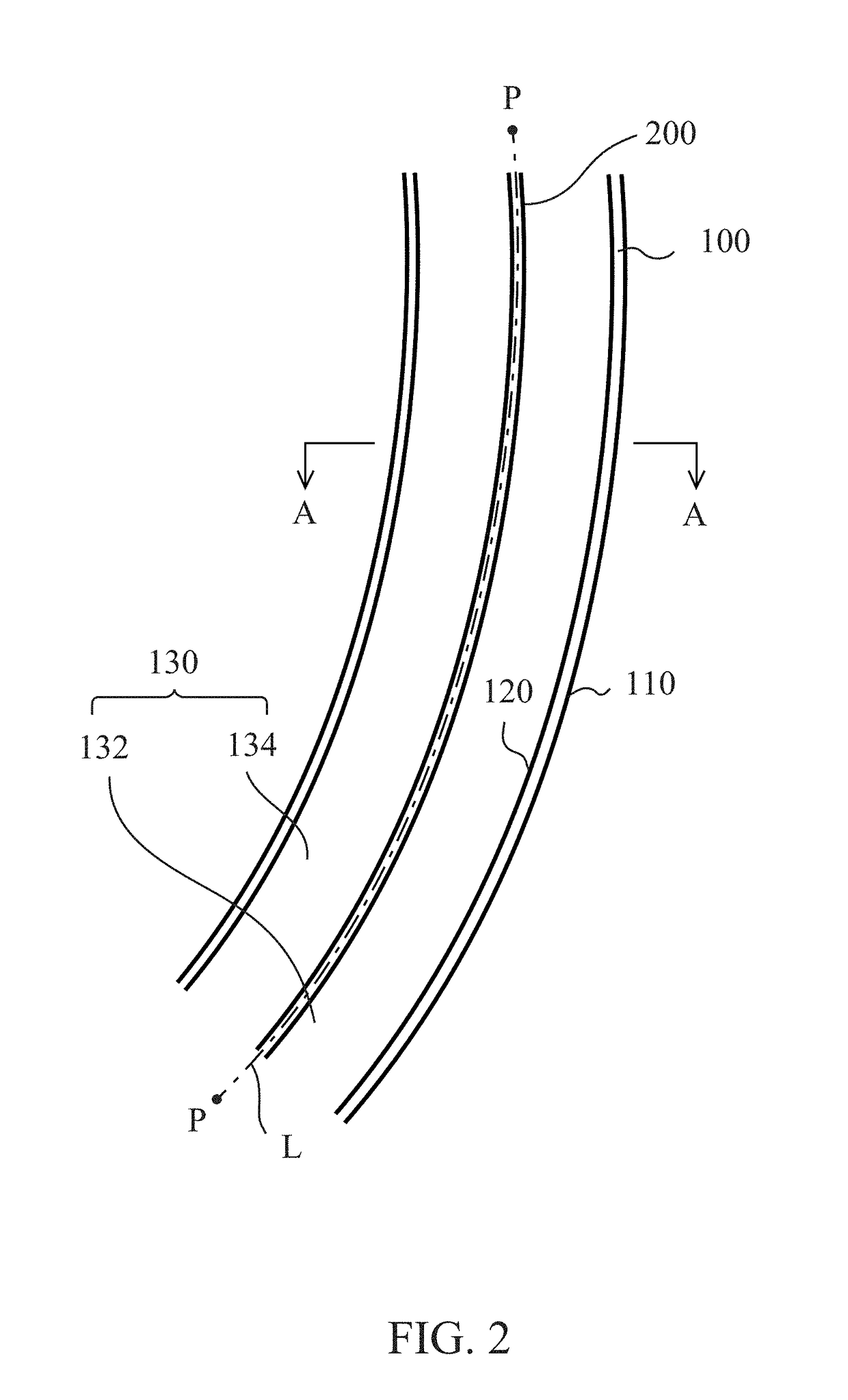
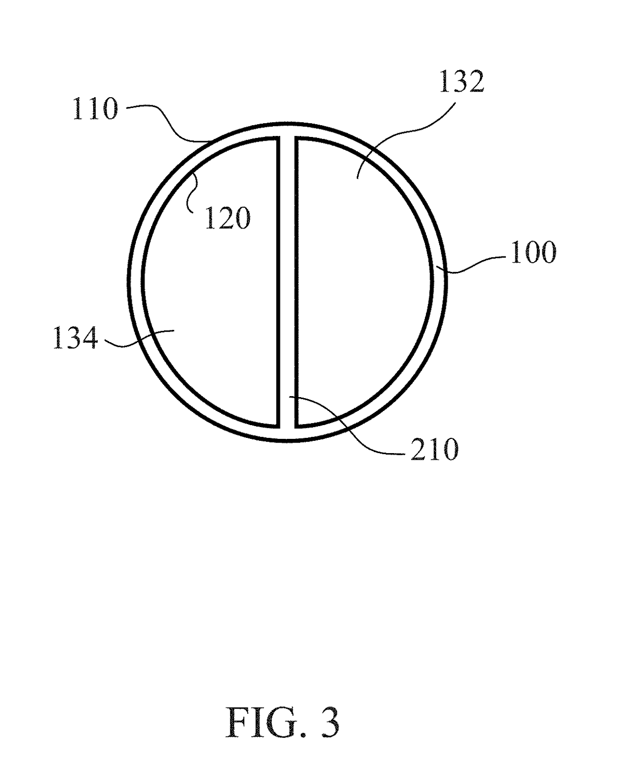
[0030]The snorkeling tube structure 10 may be manufactured by blow molding (specific technical contents thereof will be described later), so the shape, size and / or strength of the snorkeling tube structure 10 are all different from conventional snorkeling tubes manufactured by injection molding and the snorkeling tube structure 10 can meet different requirements. FIGS. 2 and 3 together are respectively a longitudinal cross-sectional ...


PUM

PropertyMeasurementUnit
Thicknessaaaaaaaaaa
Thicknessaaaaaaaaaa
Thicknessaaaaaaaaaa

Abstract

A snorkeling tube structure with a tube body and a partition portion is provided. The tube body is formed along an axis and has an outer surface and an inner surface which encircles the axis to define an air passage; the axis includes a curved section. The partition portion is formed integrally with the tube body along the axis, and disposed on the inner surface of tube body to divide the air passage into an intake passage and an outtake passage. A method of manufacturing a snorkeling tube structure is also provided, including the following steps: forming a parison including a first passage and a second passage; placing the parison in a mold cavity; injecting air into the first and second passages to inflate the parison towards a wall of the mold cavity; and removing the inflated parison from the mold to get a snorkeling tube structure.

Description

CROSS-REFERENCES TO RELATED APPLICATIONS[0001]This application claims priority to Taiwan Patent Application No. 106127665 filed on Aug. 15, 2017, which is hereby incorporated by reference in its entirety.BACKGROUND OF THE INVENTIONField of the Invention[0002]The present invention provides a snorkeling tube structure and a method of manufacturing the same. In particular, the present invention provides a snorkeling tube structure for use in a snorkeling or diving sport equipment and a method of manufacturing the same.Descriptions of the Related Art[0003]Snorkeling tubes are widely used in snorkeling or diving sports and are generally combined with a mouthpiece portion or a mask so that a user can breathe when underwater. To achieve this purpose, snorkeling tubes are generally long tubes with an end thereof above the water.[0004]A tube body of a conventional snorkeling tube only has a single air passage, so the fresh air above the water that is inhaled by the user and the exhaust air c...

Claims


Application Information

Patent Timeline
IPC IPC(8): B63C11/20B29C49/06B29C49/00
CPCB63C11/205B29C49/06B29C49/0084B29C2049/0089B29L2023/004B63C2011/165B29L2031/5254B29B11/14B29C49/0042B29C49/04B29C2949/0746B29C2949/075B29C2949/08B29C49/071B29C2949/0715
Inventor SHIUE, CHIH-CHENG
Owner QBAS CO LTD
Why Eureka
Try Eureka