Decant device

a decanting device and wine bottle technology, applied in the field of wineware, can solve the problems of inability to widely use the inability to place the conventional decanting device on the wine bottle, and the inability to solve the problem, so as to improve the decanting effect and prolong the time

Inactive Publication Date: 2019-02-28
LIU CHANG HSIEN
View PDF1 Cites 1 Cited by
  • Summary
  • Abstract
  • Description
  • Claims
  • Application Information

AI Technical Summary

Benefits of technology

[0006]One object of the present invention is to provide a decant device which is assembled on a drinking vessel. The decant device can be widely used for carrying on wines from wine bottles with different shapes and for decanting the wines. Furthermore, the through holes of the decant device are projecting downwardly, so that the wines in the decant device can be in contact with the ambient air with a greater surface area and in a longer time, thereby improving the decanting effect.

Problems solved by technology

However, the conventional decant device is just suitable for a wine bottle in which the size of the bottle mouth 5 is corresponding to the tubular body 4; otherwise, the conventional decant device cannot be positioned on the wine bottle.
As a result, the conventional decant device cannot be widely utilized.
Therefore, how to solve the problem is an issue.

Method used


Image

  • Decant device
  • Decant device
  • Decant device

Examples


first embodiment

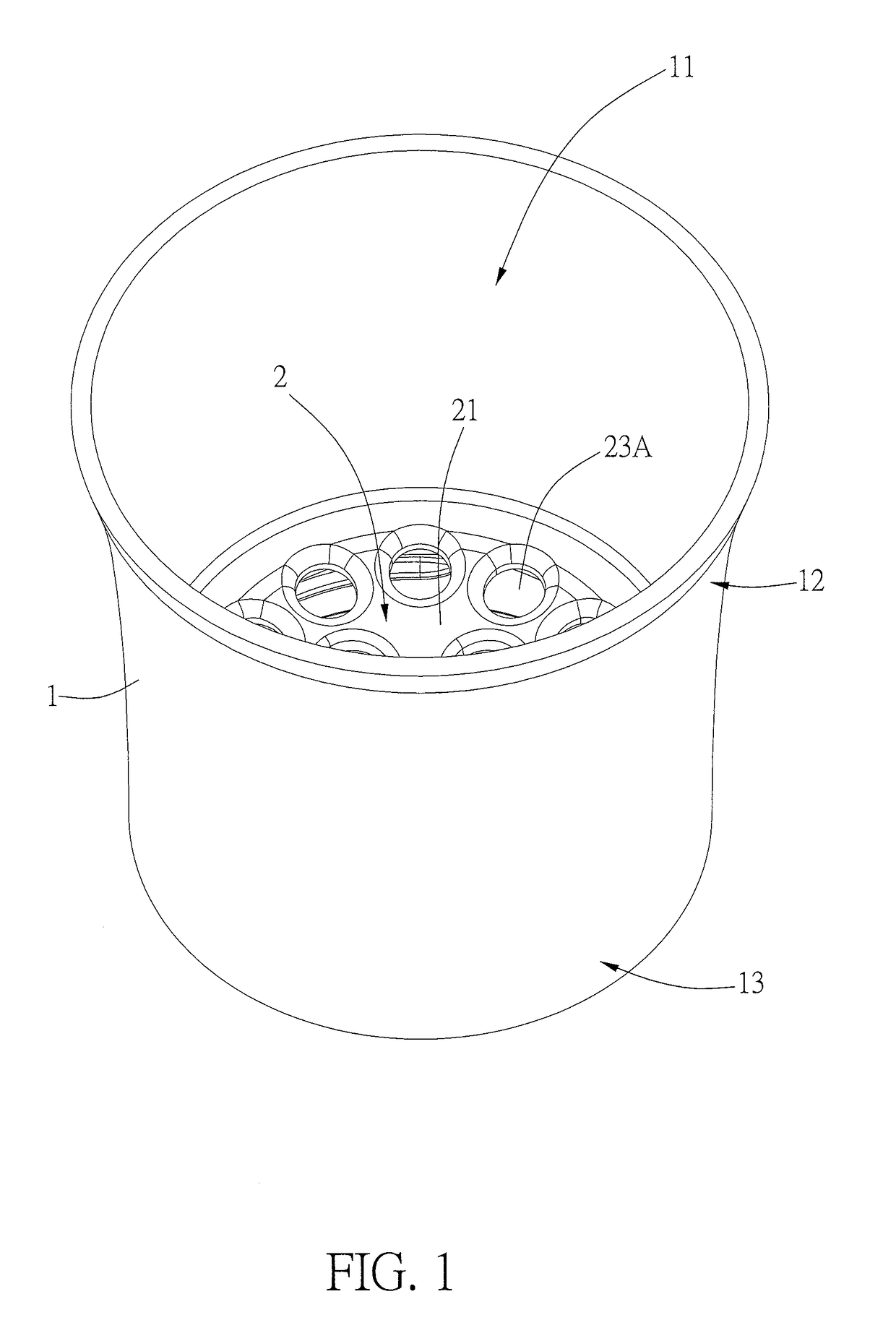
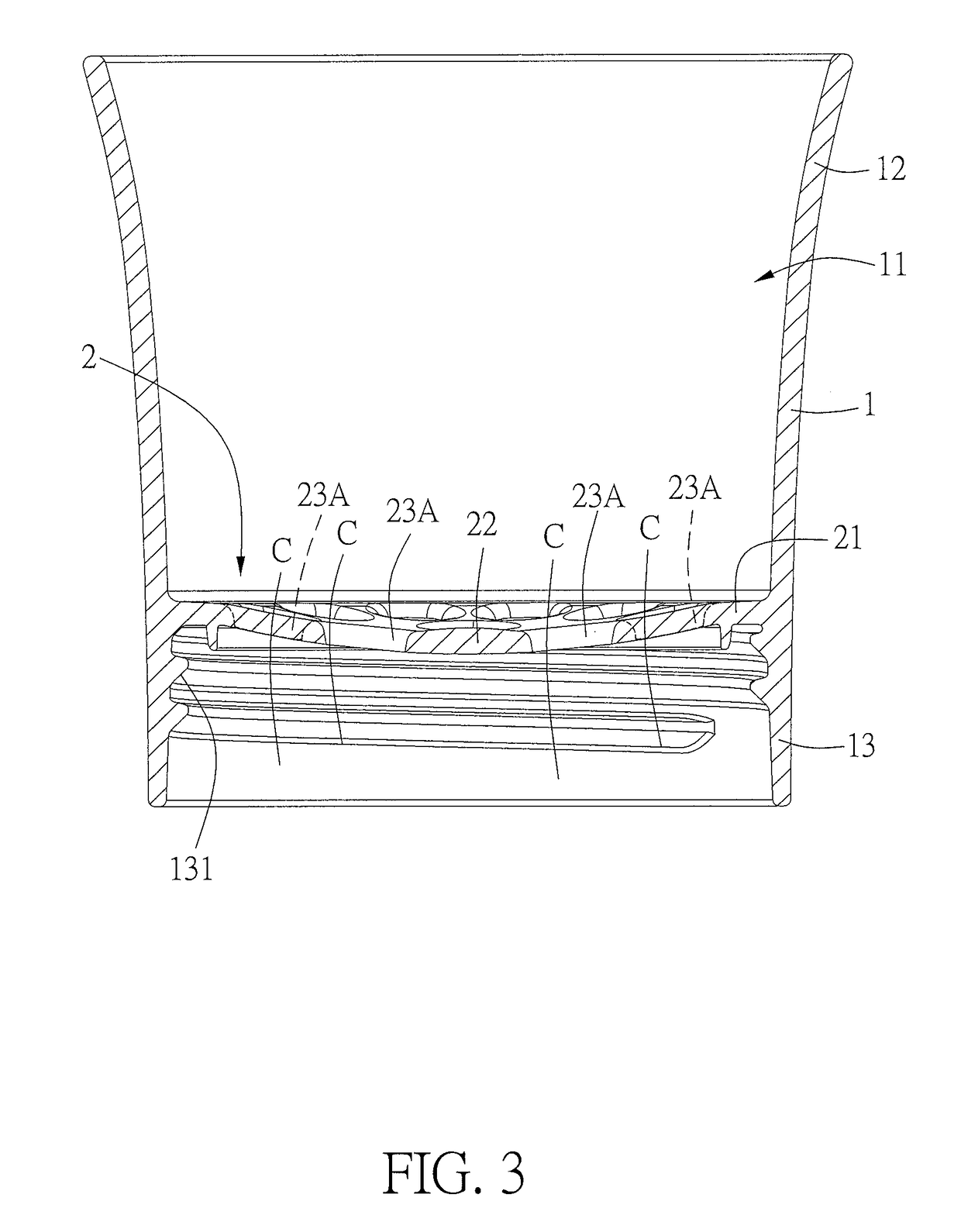
[0025]Please refer to FIGS. 1 to 3, illustrating a decant device according to the present invention. The decant device comprises a hollowed tubular body 1 enclosing a flow channel 11. An upper end 12 and a lower end 13 of the tubular body 1 are open. The bore size of the upper end 12 increases gradually from bottom to top. The lower end 13 is used to be combined with a mouth of a cup. In this embodiment, the lower end13 has threading portion 131, and the threading portion 131 is used to combine with the corresponding threading portion of the mouth of the cup.

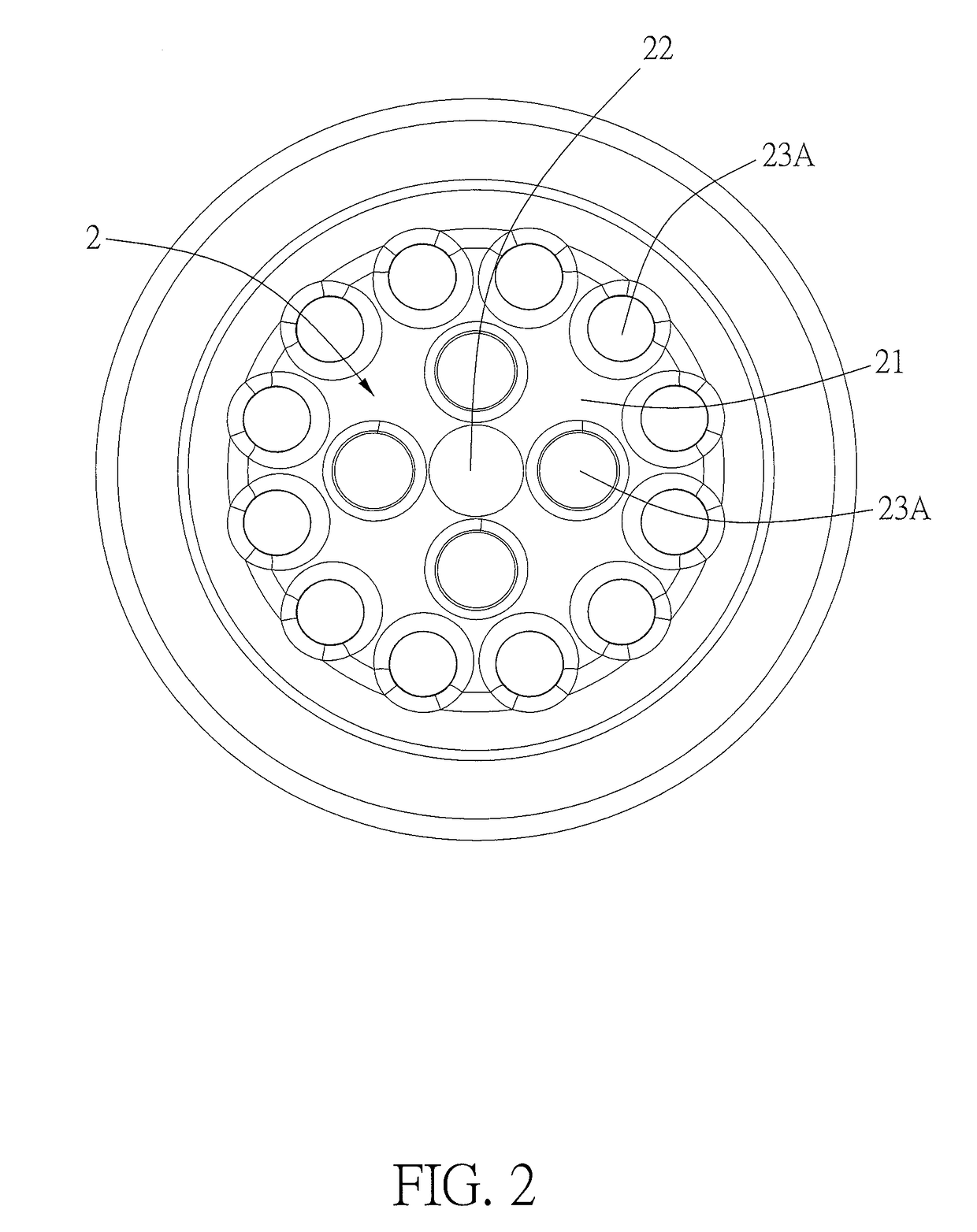
[0026]Moreover, a dispenser 2 is assembled in the tubular body 1. The dispenser 2 is laterally connected to an inner wall of the tubular body 1 and laterally located across the flow channel 11. The dispenser 2 has a plate body 21, and a periphery of the plate body 21 is connected to the inner wall of the tubular body 1. The plate body 21 has a center portion 22, and the plate body 21 has a curved surface protruding from the cent...

second embodiment

[0030]Please refer to FIGS. 5 and 6, illustrating a decant device according to the present invention. In this embodiment, the shape of the through hole is different. In this embodiment, the plate body 21 has through holes comprising round holes 23B and curved oblong holes 23C, and the curved oblong holes 23C are located at an outer side of the round holes 23B. According to the shape of the through holes, the decant device of this embodiment is suitable for fruit wines.

third embodiment

[0031]Please refer to FIGS. 7 and 8, illustrating a decant device according to the present invention. In this embodiment, the shape of the through hole is different. In this embodiment, the plate body 21 has through holes being fan-shaped through holes 23D. Further, as shown in FIG. 9, two sides of each of the fan-shaped through holes 23D form inclined surfaces. According to the shape of the through holes, the decant device of this embodiment is suitable for grape wines. Moreover, in this embodiment, the center portion 22 is protruding upwardly, and a plurality of grooves 221 is extending from the center portion around the center portion 22. Therefore, when the red wine is pouring to the center portion 22, the red wine can be spread everywhere and flowing to the fan-shaped through holes 23D along the grooves 221, thereby achieving the decanting effect.


PUM

PropertyMeasurementUnit
bore sizeaaaaaaaaaa
sizeaaaaaaaaaa
shapesaaaaaaaaaa

Abstract

A decant device includes a tubular body being hollowed and having an upper end and a lower end being open. The lower end is capable of combining with a mouth of a cup. A dispenser is assembled in the tubular body. The dispenser has a plate body laterally connected to an inner wall of the tubular body. The plate body has a center portion and the plate body has a curved surface protruding from the center portion toward the lower end. The plate body has a plurality of through holes surrounding the center portion, and an extension direction of each of the through holes is perpendicular to a corresponding portion of the curved surface where the through hole is located.

Description

BACKGROUND OF THE INVENTIONField of the Invention[0001]The present invention relates to a wineware, in particular to a decant device.Description of the Prior Art[0002]Once a decant procedure is applied to a wine (especially grape wine) before drinking, the aroma of the wine can be promoted and the acerbic taste of the wine can be softened, so that the taste of the wine would be much mellower. The principle for decanting wine is allowing the wine to contact air to oxidize the wine by a proper extent. Currently, market available decant devices are designed according to the aforementioned principle.[0003]A conventional decant device is illustrated in FIG. 10. The decant device has a tubular body 4, a T-shaped channel is assembled in the tubular body 4, and the T-shaped channel is formed by a cone-shaped wine channel 41 and an air channel 42. In operation, the tubular body 4 is inserted into the bottle mouth 5 of a wine bottle, so that the wine channel 41 is in communication with the wi...

Claims


Application Information

Patent Timeline
Patent Type & Authority Applications(United States)
IPC IPC(8): B01F3/04
CPCB01F3/04787B01F2215/0072B01F2003/04872B01F23/23412B01F33/5011B01F2101/17B01F23/236B01F23/237611
Inventor LIU, CHANG HSIEN
Owner LIU CHANG HSIEN
Why Eureka
Try Eureka