
Adjustable flywheel

a flywheel and adjustable technology, applied in the field of adjustable flywheels, can solve the problems of not having known means that allow the adjustment of the properties of the flywheel

Active Publication Date: 2019-02-28
GALIANA DOMINGUEZ EVARISTO
View PDF7 Cites 0 Cited by
  • Summary
  • Abstract
  • Description
  • Claims
  • Application Information

AI Technical Summary

Benefits of technology

This patent describes a device that allows for adjustments to the inertia of a flywheel without having to stop it. The device includes magnetic points and arms that can rotate to change the moment of inertia. This makes it easy for a technician to adapt the flywheel's operation based on different input speeds or loading conditions. The device also has conventional means to limit movement, such as stops. The technical effect is the ability to quickly and easily adjust the flywheel's performance characteristics without having to stop it.

Problems solved by technology

There are no known means that allow to adjust the properties of the flywheel such as the recommended one.

Method used


Image

  • Adjustable flywheel
  • Adjustable flywheel

Examples


Embodiment Construction

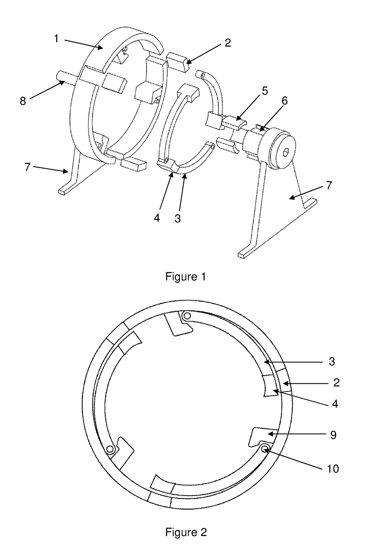
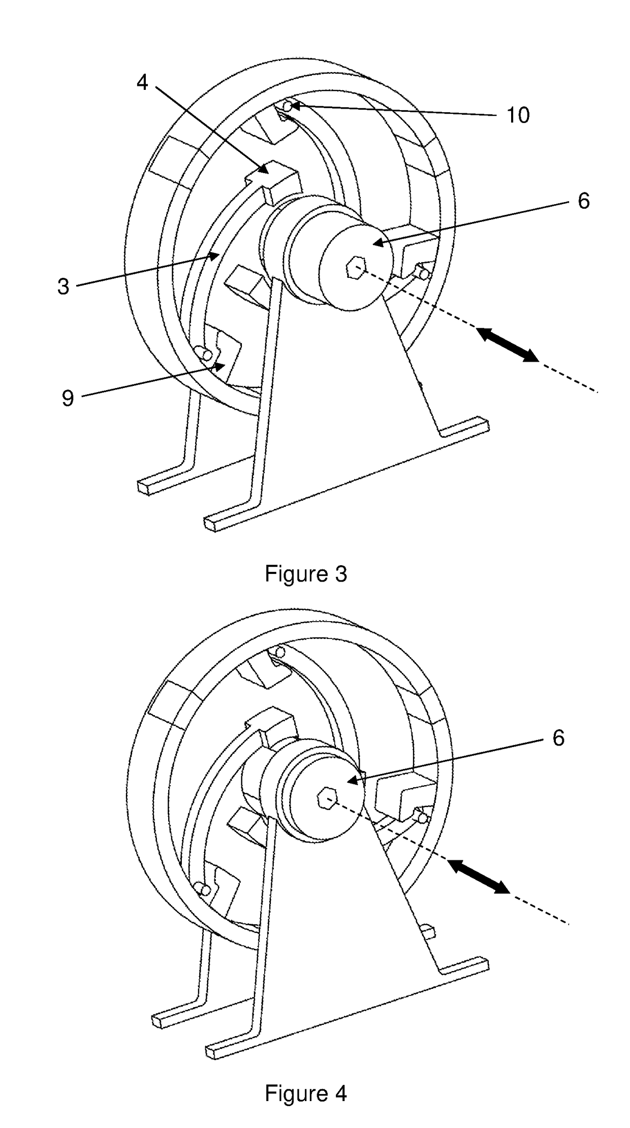
[0010]This adjustable flywheel has means that allow to adjust the characteristics of its moment of inertia without requiring it to be idle, thus obtaining an operation which can be adapted by the technician depending on the angular input speed of the flywheel or different loading conditions coupled to the same. These means are materialised by having at least two magnetic point masses housed in at least two mass-bearing arms which can rotate with regards to the rotation point located closest to the maximum diameter of the flywheel chassis, in such a way that the centrifugal force generated causes the rotation of the arms and the masses, increasing the moment of inertia of the assembly as these point masses are moved with respect to the rotation point. The chassis of the flywheel is fitted with conventional means for limiting the movement of the mass-bearing arms, such as some stops that limit the movement.

[0011]The adjustment that is carried out on the flywheel is done so by means of...


PUM


Abstract

The flywheel has the ability to vary its behaviour without having to resort to making adjustments when the unit is idle, due to which its inertia movement can be adjusted at the discretion of the technician based on the angular velocity of the system or the possible variations of the flywheel load. The flywheel has the ability to vary the distribution of its point masses due to the influence of at least one magnetic or electromagnetic field that can be modified when in operation. Aimed for the industrial sector dedicated to the construction of machinery.

Description

PURPOSE OF THE INVENTION[0001]The purpose of this invention is to provide flywheels with the ability to adapt their behaviour to a variety of fluctuations in the input power they receive and the load without having to stop the flywheel to do so.TECHNIQUE SECTOR[0002]This invention is located within the industrial sector, especially in the industries engaged in the construction of machinery.INVENTION BACKGROUND[0003]The contribution flywheels make to mechanics is widely known, given that the moment of inertia is dependent on the differential mass with respect to its rotation axis. The state of the art has followed two types of strategy, on the one hand those innovations based on modifying the turn radius of the assembly and others based on modifying this mass. Taking account of this natural classification, attention has also been paid to the innovations that allow for this adjustment to be carried out or not when the flywheel is in operation.[0004]Patent CN103470688A shows a flywheel...

Claims


Application Information

Patent Timeline
IPC IPC(8): F16F15/31H01F7/02H01F7/06
CPCF16F15/31H01F7/02H01F7/06H02N11/00H02K7/09F16F2222/06H02N11/008
Inventor GALIANA DOM NGUEZ, EVARISTO
Owner GALIANA DOMINGUEZ EVARISTO
Learn More