Magnetically operated fan device

a fan device and magnet technology, applied in the direction of dynamo-electric brake/clutch, non-positive displacement fluid engine components, liquid fuel engine components, etc., to achieve the effect of not consuming valuable and expensive electric energy

Inactive Publication Date: 2008-12-02
TSAI HSUEH LEE
View PDF7 Cites 0 Cited by
  • Summary
  • Abstract
  • Description
  • Claims
  • Application Information

AI Technical Summary

Benefits of technology

[0009]The primary objective of the present invention is to provide a fan device automatically operatable or drivable with magnetic materials or members without consuming valuable and expensive electric energy.
[0010]In accordance with one aspect of the invention, there is provided a magnetically operated fan device comprising a housing, a fan member rotatably supported on the housing, at least one first magnetic member disposed in the housing, a base supported in the housing, a follower rotatably attached to the base, and including a frame provided thereon, an axle rotatably attached to the frame of the follower, and including at least one eccentric member attached to the axle and rotated in concert with the axle, for increasing moment of inertia of the axle, a second magnetic member attached to the eccentric member, for acting with the first magnetic member of the housing, to bias and force the axle to continuously rotate relative to the frame of the follower and the housing, and a coupling device for coupling the axle to the fan member, to have the fan member to be rotated and driven by the axle and by continuously rotation of the second magnetic member and the eccentric member and the axle relative to the frame of the follower and the housing, without consuming electric energy.

Problems solved by technology

At present, the motors of the typical fan devices are all required to be driven or operated by electric energy, and may not be operated or driven without electric energy.

Method used


Image

  • Magnetically operated fan device
  • Magnetically operated fan device
  • Magnetically operated fan device

Examples


Embodiment Construction

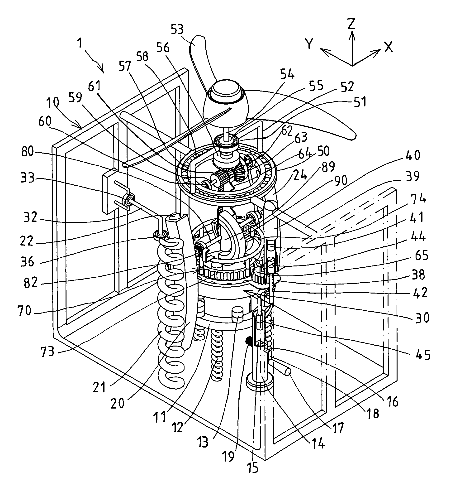
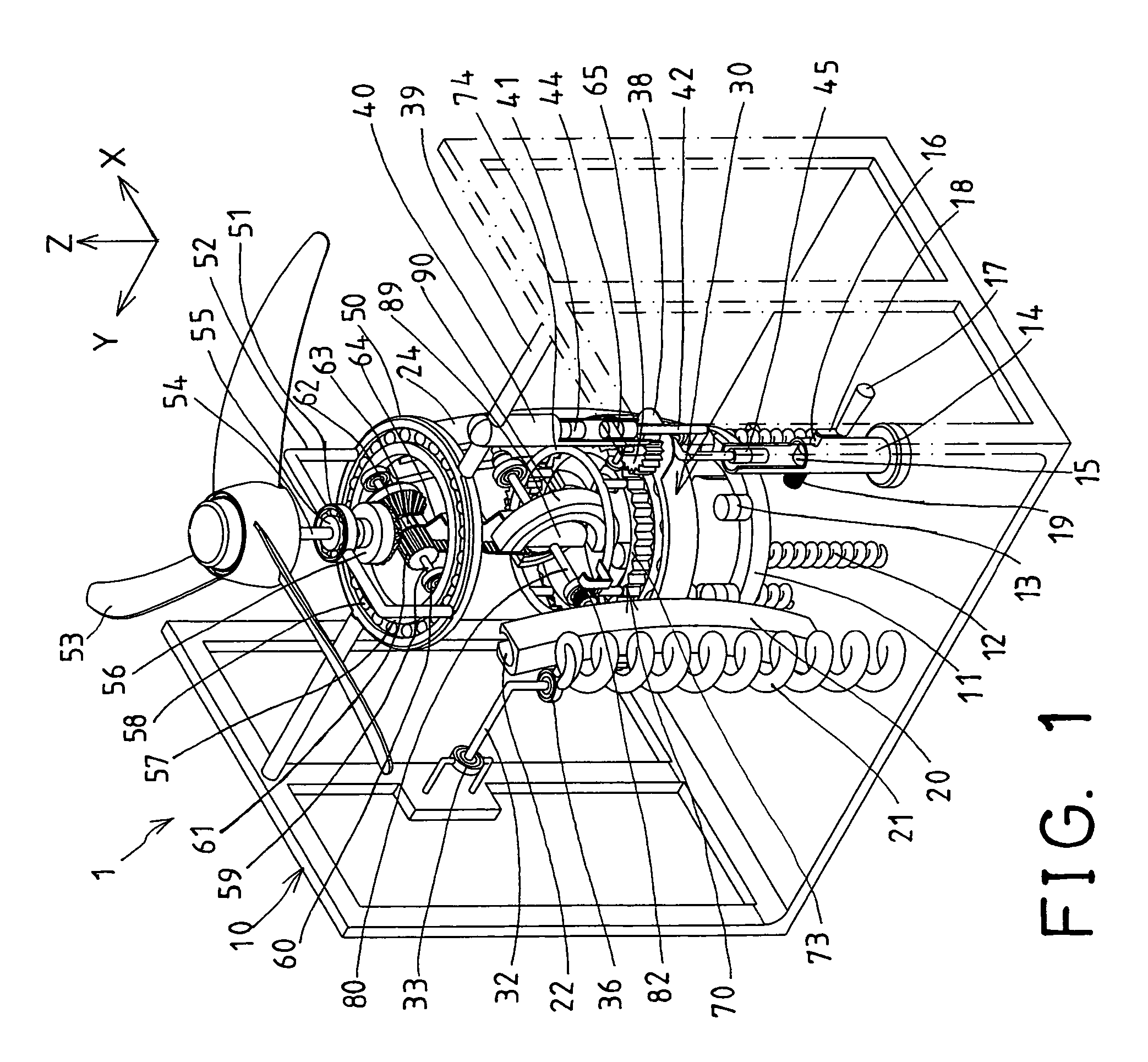
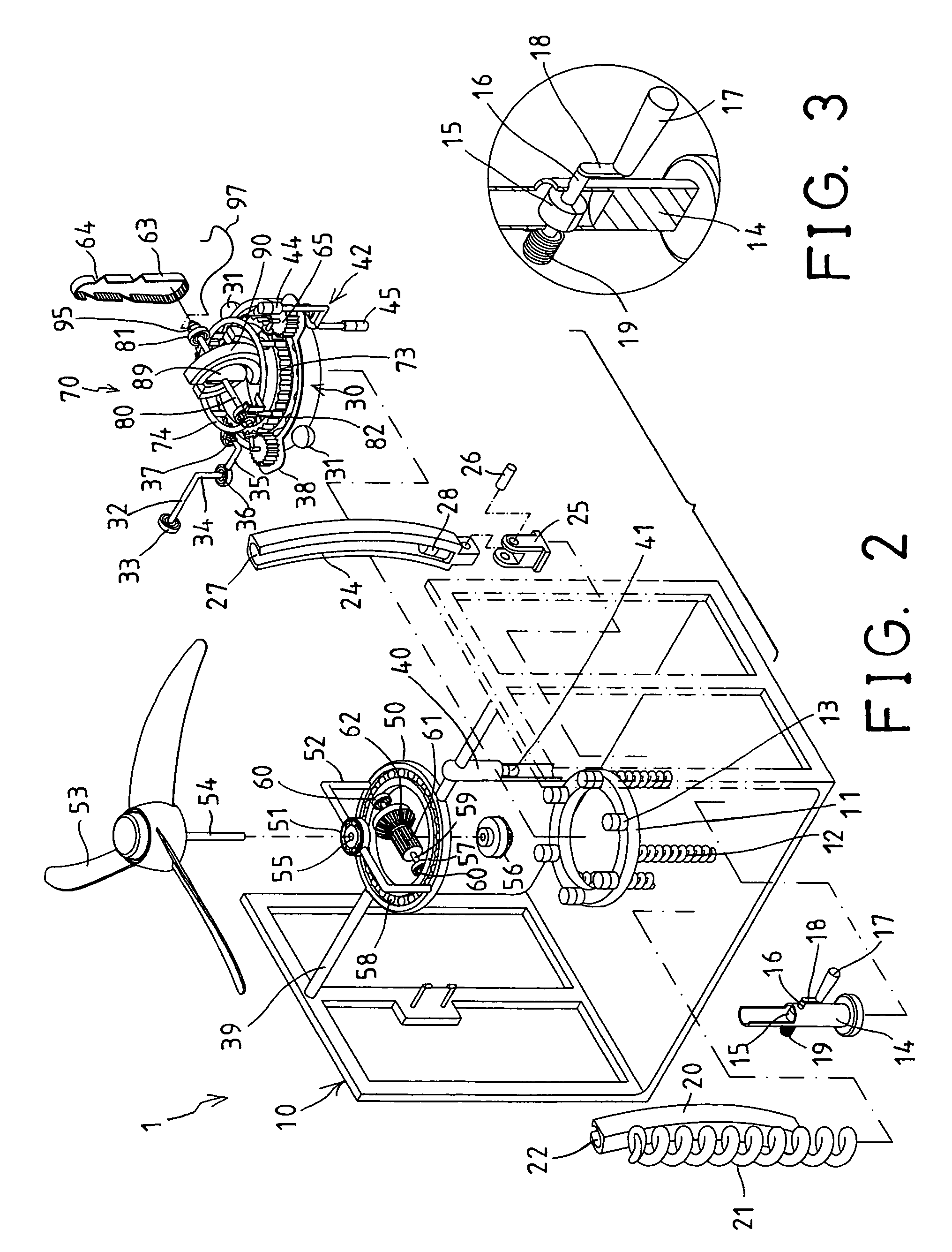
[0040]Referring to the drawings, and initially to FIGS. 1-6, a magnetically operated fan device 1 in accordance with the present invention comprises a housing 10 including a support element 11 disposed therein, and resiliently supported by one or more spring members 12, and one or more magnetic members 13 disposed on the support element 11, and including a seat 14 disposed therein.

[0041]A magnetic member 15 is disposed in and rotatably attached to the seat 14 with a rod 16, and a handle 17 is coupled to the rod 16 with a crank 18, to allow the rod 16 and thus the magnetic member 15 to be rotated relative to the seat 14 by the handle 17 via the crank 18. A spring biasing or recovering member 19 is coupled to the rod 16, in order to recover the rod 16, and thus to position the magnetic member 15 at required positions, such as to have the negative or the positive pole of the magnetic member 15 to be arranged or directed downwardly or upwardly.

[0042]A track 20, such as a curved track 20...


PUM


Abstract

A magnetically operated fan device includes a fan member rotatably supported on a housing, one or more magnetic members disposed in the housing, a base supported in the housing, a follower rotatably attached to the base and having a frame, an axle rotatably attached to the frame and having one or more eccentric members for increasing moment of inertia of the axle, one or more magnetic members attached to the eccentric member for acting with the magnetic members of the housing, to bias the axle to continuously rotate relative to the frame of the follower. A coupling device may couple the axle to the fan member, to have the fan member to be driven continuously by the magnetic members and the eccentric members.

Description

BACKGROUND OF THE INVENTION[0001]1. Field of the Invention[0002]The present invention relates to a fan device, and more particularly to a fan device automatically operatable or drivable with magnetic materials or members without consuming valuable and expensive electric energy.[0003]2. Description of the Prior Art[0004]Various kinds of typical fan devices have been developed and comprise a motor coupled to a fan member, in order to rotate or to drive the fan member to generate circulating air.[0005]For example, U.S. Pat. No. 5,304,035 to Carter discloses one of the typical fan devices which comprises a greatly reduced size or volume that may be easily attached to the users with such as cord, and to be carried by the users. The typical fan device also comprises a motor coupled to a fan member, in order to rotate or to drive the fan member to generate circulating air.[0006]U.S. Pat. No. 5,558,501 to Wang et al. discloses another typical fan device which comprises an adjustable post as...

Claims


Application Information

Patent Timeline
Patent Type & Authority Patents(United States)
IPC IPC(8): F03G7/00H02K49/00H02P15/00
CPCF04D25/02F04D25/086
Inventor SHYU, SHIN FA
Owner TSAI HSUEH LEE
Why Eureka
Try Eureka