Variable Moment Flywheel

a variable-speed system and flywheel technology, applied in mechanical equipment, machines/engines, greenhouse gas reduction, etc., can solve the problems of increasing structural load, increasing cost, and reducing so as to increase the angular velocity of the turbine, increase the moment of inertia of the system, and reduce the angular velocity of the system

Inactive Publication Date: 2022-04-07
MAIULLO DANIEL ANTHONY
View PDF2 Cites 0 Cited by
  • Summary
  • Abstract
  • Description
  • Claims
  • Application Information

AI Technical Summary

Benefits of technology

[0015]The floor of the device is shaped in the radial direction in an increasing angle to the horizontal approaching ninety degrees. This part of the device is called the first bowl. As the angle gets close to ninety degrees, it rapidly drops to a much lower angle. This part of the device is called the first shelf. Then the angle increases, approaching ninety degrees again. This part of the device is called the second bowl. This shape repeats as many times as is required by the specific turbine, charging system, and circumstances for which the invention is designed. This repeating shape of bowls and shelves allows for a kind of “gearing”: as excess energy is input into the device, it increases the angular velocity of the turbine, and thereby that of the invention. The mass is therefore pushed up the walls of the bowl in an outward radial direction until it flows over the shelf and into the next bowl. After the mass flows over the shelf, it rapidly flows outward, thereby increasing the moment of ine...

Problems solved by technology

With all of these devices, the excess power of the wind is lost and is not used to generate electrical or mechanical energy.
A fixed speed wind turbine generator system must be very mechanically robust, adding to cost.
Because the rotor speed cannot be varied, fluctuations in wind speed translate directly into drive train torque fluctuations, causing higher structural loads than with variable speed systems.
A...

Method used


Image

  • Variable Moment Flywheel
  • Variable Moment Flywheel
  • Variable Moment Flywheel

Examples


Embodiment Construction

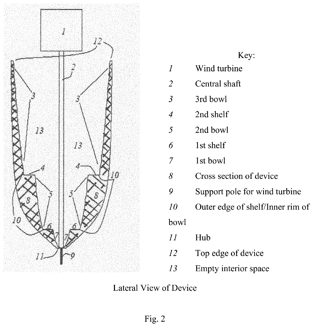
[0021]Mathematics. The mathematics of the invention is derived as follows: Picture a bowl-shaped device with inclined sides spinning about its axis. In the device are radially oriented vertical walls. Also in the device is a fluid substance (mass) which moves up and down the sides. The fluid mass can be any appropriate liquid or set of small spherical (or non-spherical) solid particles. As the device spins on its axis, this mass is pushed around by the radially oriented vertical walls. As the angular velocity increases, the mass moves further out radially and up the inclined sides of the device. The total energy of the device is the sum of the potential energy and kinetic energy.

[0022]The potential energy, U=mgh, where m is the mass, g is the acceleration due to gravity, and h is the height of the mass from the base of the device.

[0023]The kinetic energy, K=½ω2r2m=½ω2I, where ω is the mass; w is the angular velocity of the device and, by virtue of the vertical walls in the device, t...


PUM


Abstract

A method for storage of excess energy which would otherwise be lost, the regulation of angular velocity, and prevention of excessive velocities is disclosed. The device consists of a bowl shaped container, divided into sections by radially oriented vertical walls, which holds a fluid (any appropriate liquid or set of small solid particles), and spins on its vertically oriented axis at various angular velocities. The floor of the device is formed in successive shapes of bowls and shelves, which allows for a kind of “gearing”. The invention allows more and more energy to be input into the device while the angular velocity is regulated within a particular range. A typical embodiment of the invention would include its attachment by a shaft at the axis to a vertical axis wind turbine.

Description

CROSS-REFERENCE TO RELATED APPLICATIONS[0001]Provisional Application 62 / 133,440 Mar. 15, 2015;[0002]Non-Provisional application Ser. No. 15 / 062,930 Mar. 7, 2016; U.S. Pat. No. 10,221,917 (parent patent application)[0003]Non-Provisional application Ser. No. 16 / 286,740 Feb. 27, 2019; U.S. Pat. No. 11,009,099 (parent patent application continuation in part).STATEMENT REGARDING FEDERALLY SPONSORED RESEARCH OR DEVELOPMENT[0004]Not applicable.REFERENCE TO SEQUENCE LISTING, A TABLE, OR A COMPUTER PROGRAM LISTING COMPACT DISC APPENDIX[0005]Not applicable.TECHNICAL FIELD[0006]The present invention relates generally to a method and a flywheel apparatus for absorbing and storing excess fluctuating energy and power by varying the moment of inertia of the flywheel.BACKGROUND[0007]All devices designed to convert the kinetic energy of wind into mechanical and / or electrical energy, commonly called “wind turbines”, need to contend with the fluctuating nature of the wind. All existing wind turbine de...

Claims


Application Information

Patent Timeline
IPC IPC(8): F03D9/12
CPCF03D9/12F05B2270/101F05B2260/421F16F15/31Y02E10/72Y02E60/16Y02E70/30F05B2240/211
Inventor MAIULLO, DANIEL ANTHONY
Owner MAIULLO DANIEL ANTHONY
Why Eureka
Try Eureka