Cyclone device

A technology of cyclone separator and swirling airflow, applied in cyclone devices, separation methods, combined devices, etc., can solve problems such as speed reduction, and achieve the effect of improving powder collection efficiency

Inactive Publication Date: 2015-12-09
SHIZUOKA PLANT
View PDF8 Cites 7 Cited by
  • Summary
  • Abstract
  • Description
  • Claims
  • Application Information

AI Technical Summary

Problems solved by technology

Moreover, the powder mixed in the airflow is separated from the airflow under the action of centrifugal force and collides with the inner wall surface of the cyclone separator body 21, and the speed decreases.

Method used


Image

  • Cyclone device
  • Cyclone device
  • Cyclone device

Examples


no. 1 Embodiment

[0048] Hereinafter, the cyclone device according to the first embodiment of the present invention will be described with reference to the drawings.

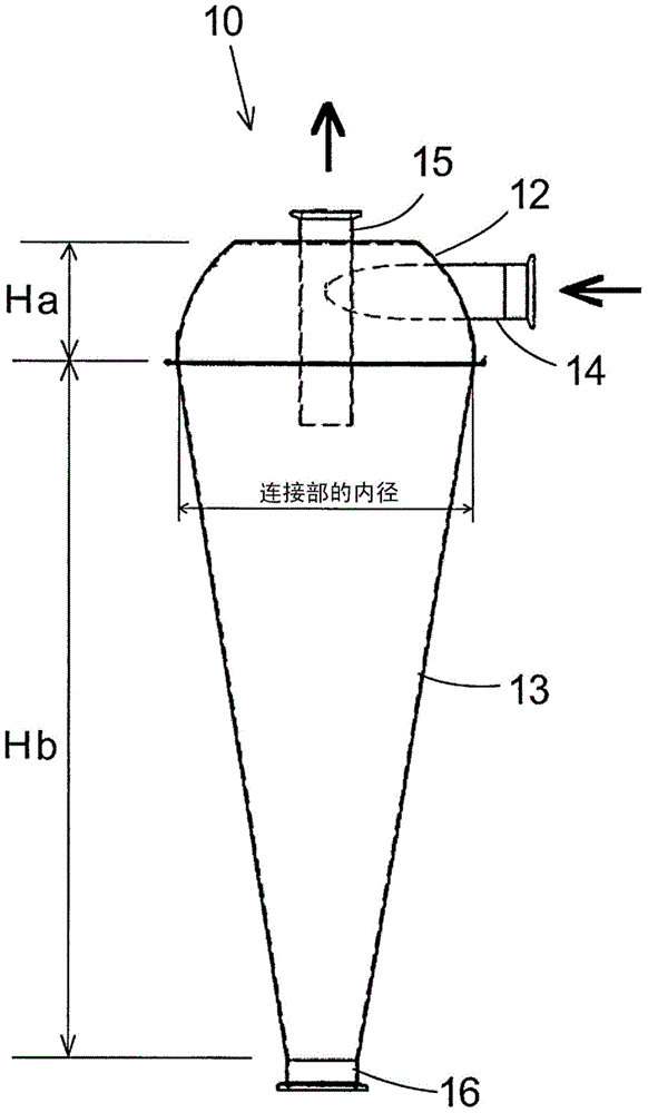
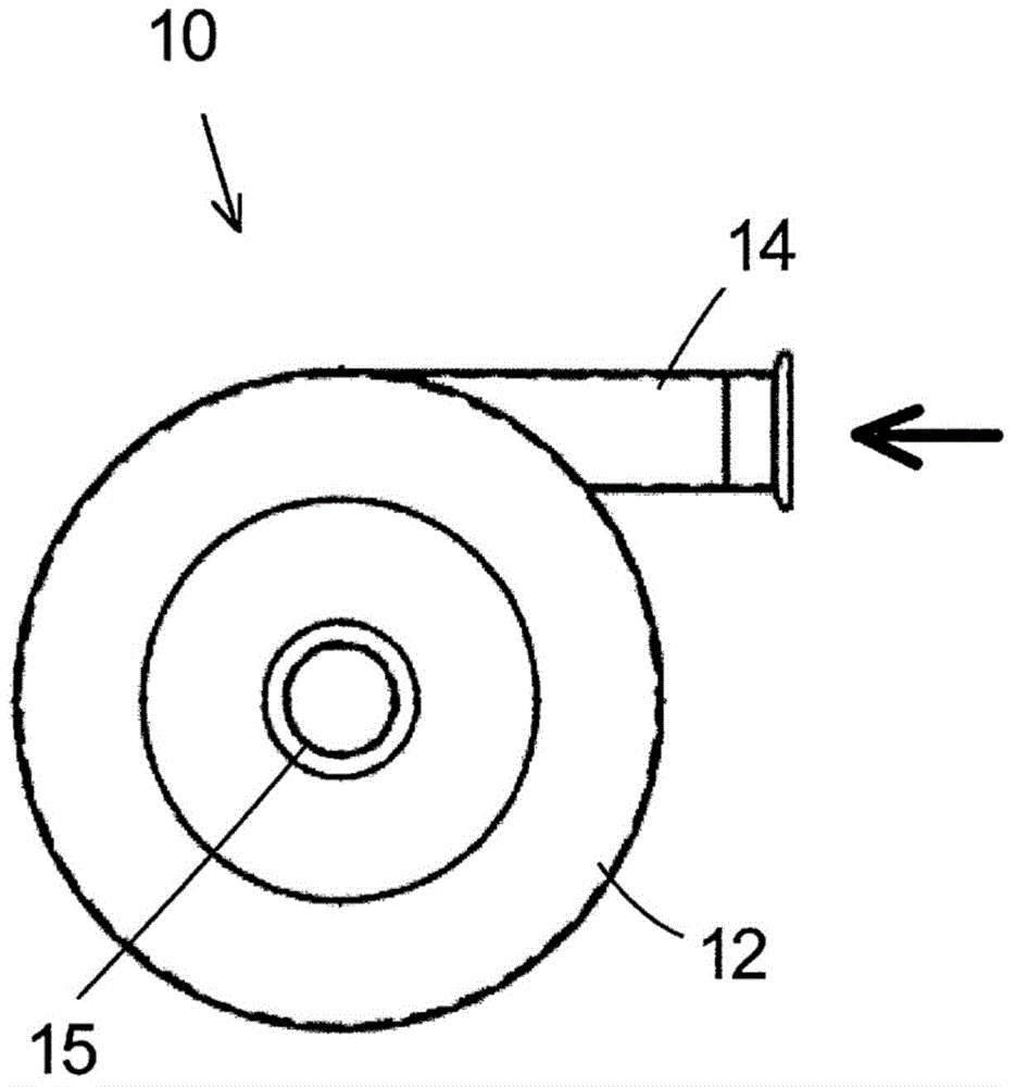
[0049] Such as figure 1 with figure 2 As shown, the cyclone device 10 of this embodiment includes an airflow introduction section 12 with an upper structure and a tapered section 13 with a lower structure.

[0050] The airflow introducing section 12 has a hemispherical internal structure with a diameter gradually expanding downward. The airflow containing powder is introduced from the airflow introducing portion 14 provided at one end of the airflow introducing section 12 in the tangential direction of the airflow introducing section 12, and thus along the A whirling airflow is generated on the inner wall surface of the airflow introducing section 12.

[0051] The tapered section 13 of the lower structure is connected to the lower end of the hemispherical air flow introducing section 12 and has an inverted cone-shaped internal structu...

no. 2 Embodiment

[0090] Next, the second embodiment of the present invention will be described.

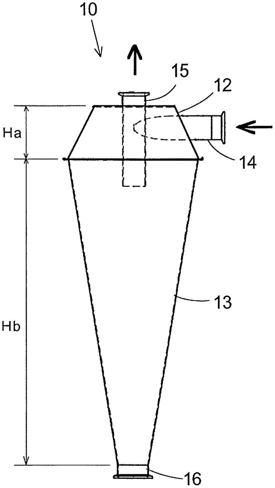
[0091] Image 6 Is a front cross-sectional view showing the cyclone device 110 of this embodiment, Figure 7 Is its top view.

[0092] As shown in these figures, the cyclone device 110 of this embodiment includes: an airflow introduction section 112, which is hemispherical and gradually expands its diameter downward; and a tapered section 113, which is in an inverted cone shape and is connected to the airflow introduction section. The lower end is connected with the lower end and the diameter is gradually reduced downward; and the powder collection section 116 is connected with the lower end of the tapered section 113.

[0093] In this embodiment, the airflow introduction section 112 is also provided with: an airflow introduction part 114, which is used to introduce the airflow containing powder into the device; and an airflow discharge part 115, which is used to complete the separation of the powder. T...


PUM

PropertyMeasurementUnit
particle diameteraaaaaaaaaa

Abstract

Provided is a cyclone device with which the efficiency in separating out and collecting a fine powder of sub-micron size can be increased. The cyclone device is for separating out and collecting, from a swirling airflow, a powder mixed into the airflow, and is characterized by being provided with an airflow introduction section (12) that has an airflow introduction part (14) for introducing a powder mixture airflow from the tangential direction and that gradually increases in diameter going downward, and an inverted cone-shaped conical section (13) that is connected to a lower end of the airflow introduction section (12) and gradually decreases in diameter going downward.

Description

Technical field [0001] The invention relates to a cyclone separator device capable of collecting fine powder in an airflow with a higher collection rate. Background technique [0002] Conventionally, the cyclone device 20 used as a device for classifying powder in an air stream is known as Picture 9 A tangential inlet type cyclone device having a cylindrical upper structure (cyclone body 21) and an inverted cone-shaped lower structure (taper section 22) as shown. [0003] In this cyclone device, the airflow mixed with the powder is introduced from the airflow introduction part 23 in the tangential direction of the cyclone body 21 to form a vortex. Furthermore, the powder mixed in the air flow is separated from the air flow by the centrifugal force and collides with the inner wall surface of the cyclone body 21, and the speed is reduced. [0004] After that, the powder that has collided with the inner wall surface of the cyclone body 21 and decelerated falls under the action of gravi...

Claims


Application Information

Patent Timeline
Patent Type & Authority Applications(China)
IPC IPC(8): B04C5/081
CPCB04C5/081B01D45/12B04C5/04B01D50/20B01D45/16B04C3/06
Inventor 户田泰宽
Owner SHIZUOKA PLANT
Why Eureka
Try Eureka