Vibrating gyroscope and angular velocity sensor

a technology of angular velocity sensor and vibrating gyroscope, which is applied in the direction of acceleration measurement using interia force, turn-sensitive devices, instruments, etc., can solve the problems of increasing the number of parts, and reducing the height of the angular velocity sensor, so as to reduce the height and the effect of the sensor

Inactive Publication Date: 2005-06-21
MURATA MFG CO LTD
View PDF9 Cites 6 Cited by
  • Summary
  • Abstract
  • Description
  • Claims
  • Application Information

AI Technical Summary

Benefits of technology

[0009]In order to solve the problems described above, preferred embodiments of the present invention provide a vibrating gyroscope constructed so as to have reduced height and an angular velocity sensor including the vibrating gyroscope.

Problems solved by technology

However, when constructed in this way, there is a problem in that only the vibrating gyroscope equipped with a vibrator with a large length protrudes more than other parts on the mounting.
However, if the overall length of the vibrator is reduced, since the resonance frequency increases and the sensitivity and SN ratio are deteriorated, it becomes impossible to detect the rotational angular velocity with a high degree of precision.
Moreover, although it has been considered to make a board on which the vibrating gyroscope is mounted separated from the main board and to make wiring connections by using a flexible printed circuit board, etc., such a construction increases the number of parts and becomes complicated, and as a result, an increase in cost is inevitable.

Method used


Image

  • Vibrating gyroscope and angular velocity sensor
  • Vibrating gyroscope and angular velocity sensor
  • Vibrating gyroscope and angular velocity sensor

Examples


first preferred embodiment

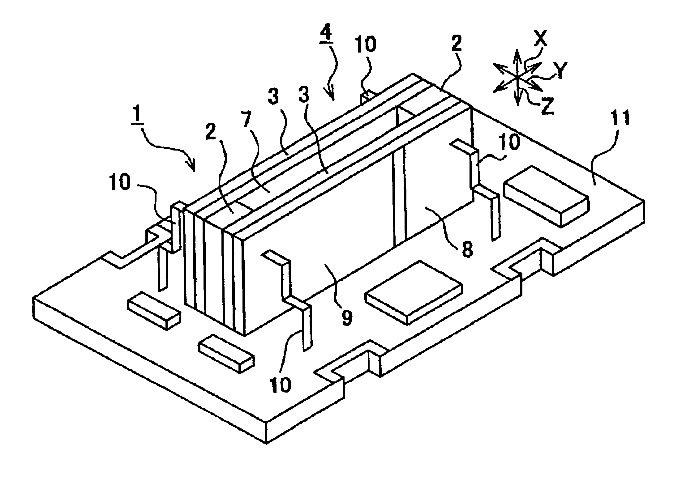
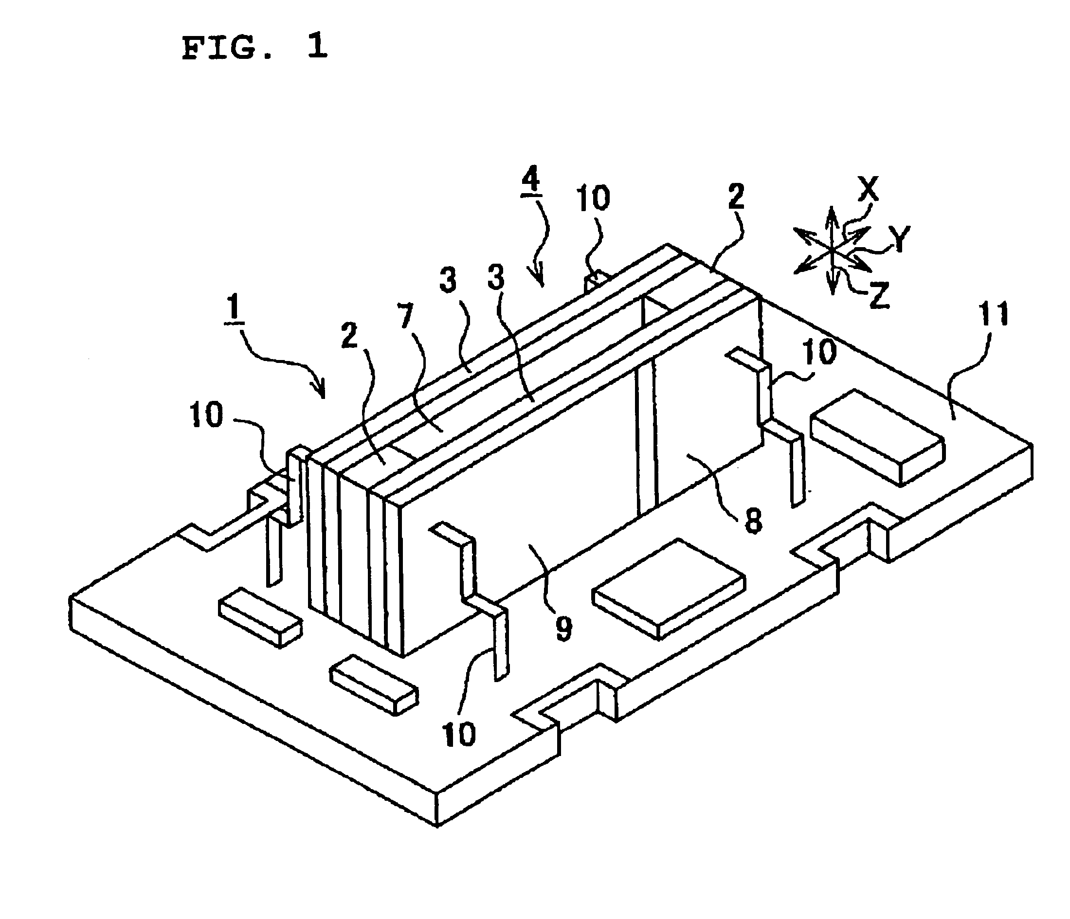
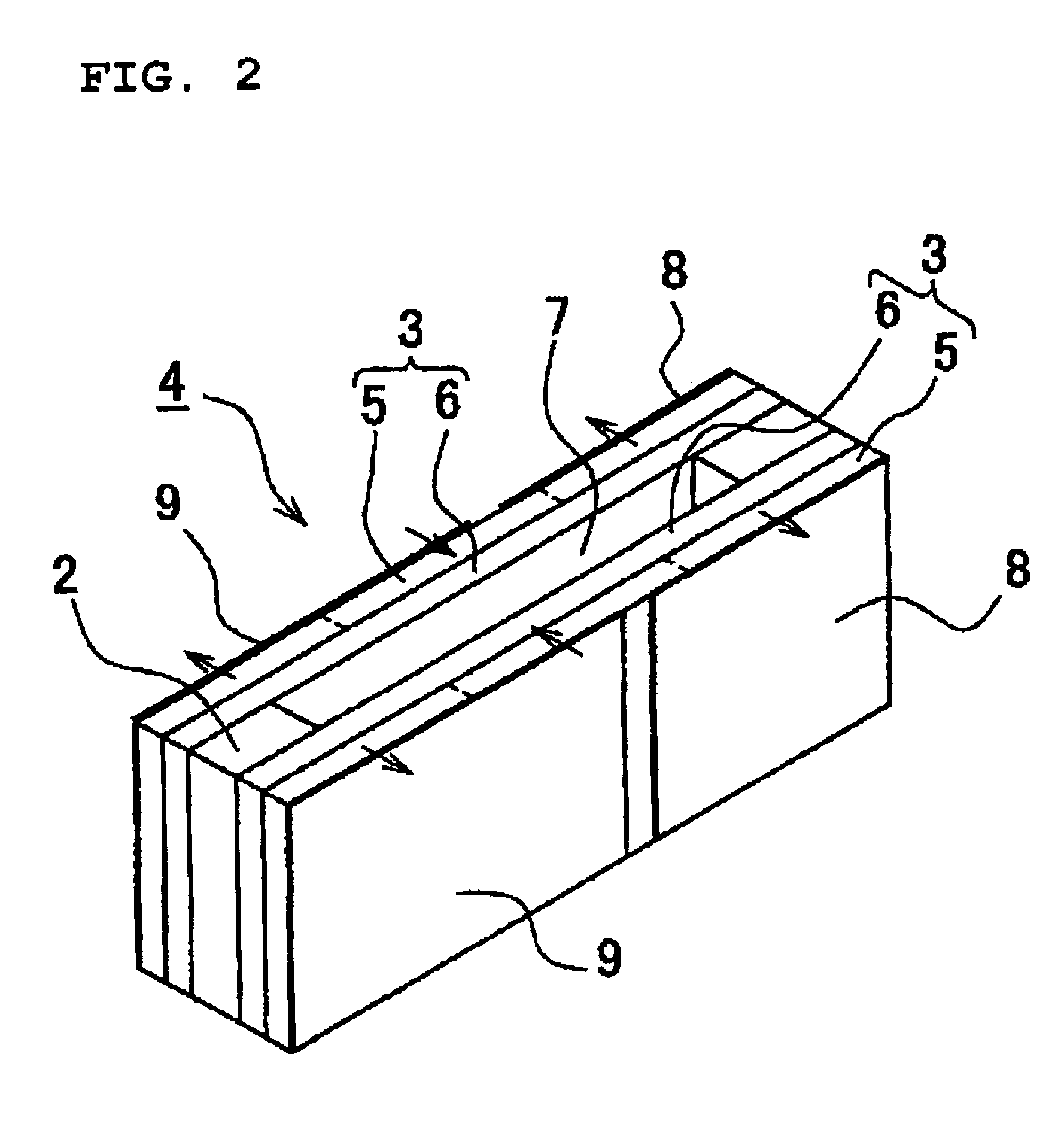
[0036]FIG. 1 is a perspective view showing the whole construction of a vibrating gyroscope according to a first preferred embodiment of the present invention, FIG. 2 is a perspective view showing the whole construction of a vibrator with which the vibrating gyroscope is equipped, and FIG. 3 is a schematic illustration showing the construction of essential parts of the vibrating gyroscope including a drive detection circuit. FIGS. 4A to 4C are top views diagrammatically showing the operation of the vibrating gyroscope, and FIG. 5 shows the relationship between the resonance frequency of a buckling vibration and the resonance frequency of a secondary bending vibration.

[0037]Furthermore, FIGS. 6 to 10 show the construction of first to fourth modified examples of the vibrating gyroscope according to the first preferred embodiment. Moreover, FIG. 11 shows the construction of essential parts of an angular velocity sensor constructed by using the vibrating gyroscope according to the first ...

second preferred embodiment

[0062]FIG. 12 shows the construction of essential parts, including a drive detection circuit, of a vibrating gyroscope according to a second preferred embodiment of the present invention, FIG. 13 shows the manufacturing process of a vibrator, and FIGS. 14 to 18 show the construction of first to fifth modified examples of the vibrating gyroscope according to the second preferred embodiment of the present invention.

[0063]Since the whole construction of the vibrating gyroscope of the second preferred embodiment is basically the same as the vibrating gyroscope of the first preferred embodiment shown in FIG. 1 except that each vibrating body 41 constituting a vibrator 40 has a bimorph construction, a detailed description is omitted. Moreover, when the description is required, in FIGS. 12 to 18, the same reference numerals are used to indicate the same or equivalent parts and portions in FIGS. 1 to 11.

[0064]The vibrating gyroscope according to the present preferred embodiment includes a v...


PUM


Abstract

A vibrating gyroscope includes a vibrator having a pair of vibrating bodies, both end portions in the longitudinal direction of which are fixed together in the thickness direction by intermediate parts and the vibrator is supported such that a secondary bending vibration with both ends free in the thickness direction of the vibrating bodies can be performed. The vibrating gyroscope also includes a driver for causing the vibrating bodies to perform buckling vibrations in opposite directions, and a detector for detecting the magnitude of the secondary bending vibration of the vibrator. The resonance frequency of the secondary bending vibration is close to the frequency of the buckling vibrations.

Description

BACKGROUND OF THE INVENTION[0001]1. Field of the Invention[0002]The present invention relates to a vibrating gyroscope and angular velocity sensor, and more particularly, to the construction of a vibrating gyroscope having a greatly reduced height, and to the construction of an angular velocity sensor having the vibrating gyroscope.[0003]2. Description of the Related Art[0004]Up to now, in navigation systems and car body control systems used in cars, since it is required to confirm the yaw direction of a car, that is, the turning direction of the body of the car, a rotational angular velocity about the vertical axis perpendicular to the traveling surface (ground) is detected. To detect the rotational angular velocity, an angular velocity sensor equipped with a vibrating gyroscope is utilized, and such a vibrating gyroscope generally contains a pole or tuning-fork vibrator (see Japanese Unexamined Patent Application Publication No. 8-292033 and Japanese Unexamined Patent Application ...

Claims


Application Information

Patent Timeline
Patent Type & Authority Patents(United States)
IPC IPC(8): G01C19/56G01C19/5642G01C19/574
CPCG01C19/5642
Inventor FUJIMOTO, KATSUMI
Owner MURATA MFG CO LTD
Why Eureka
Try Eureka