Web oiler speed control

a technology of oiler speed control and web oil, which is applied in the direction of instruments, electrographic process equipment, optics, etc., can solve the problems of premature failure of the fuser roller, undesirable image defects, and softening of the surface of the receiver member, and achieve the effect of reducing the angle of the take-up roll

Inactive Publication Date: 2005-08-11
EASTMAN KODAK CO
View PDF4 Cites 9 Cited by
  • Summary
  • Abstract
  • Description
  • Claims
  • Application Information

AI Technical Summary

Benefits of technology

[0006] In view of the forgoing discussion, it is the object of the present invention to provide for maintaining the linear velocity of release oil impregnated web oiler as the oil impregnated web is wound onto a driven take-up roll. When a new oil impregnated web is installed, the take-up roll is initially driven at an angular velocity to yield the predetermined optimum linear velocity of the oil impregnated web. The angular velocity of the take-up roll is decreased according to the invention so as to maintain constant the linear velocity of the oil impregnated web as the release oil impregnated web is wound onto the take-up roll.

Problems solved by technology

The pigmented marking particles of the transferred image on the surface of the receiver member soften and become tacky in the heat.
The offset marking particles will build up on the fuser roller and lead to undesirable image defects and / or premature failure of the fuser roller.
If the release oil delivery rate exceeds the optimum rate, excessive release oil will build up on the fuser roller.
The excess release oil will be carried away by the receiver member also causing image quality defects and / or release oil contamination of the photoconductive member if the receiver member is returned to the imaging section for transfer of a marking particle image to the opposite side.

Method used


Image

  • Web oiler speed control
  • Web oiler speed control

Examples


Embodiment Construction

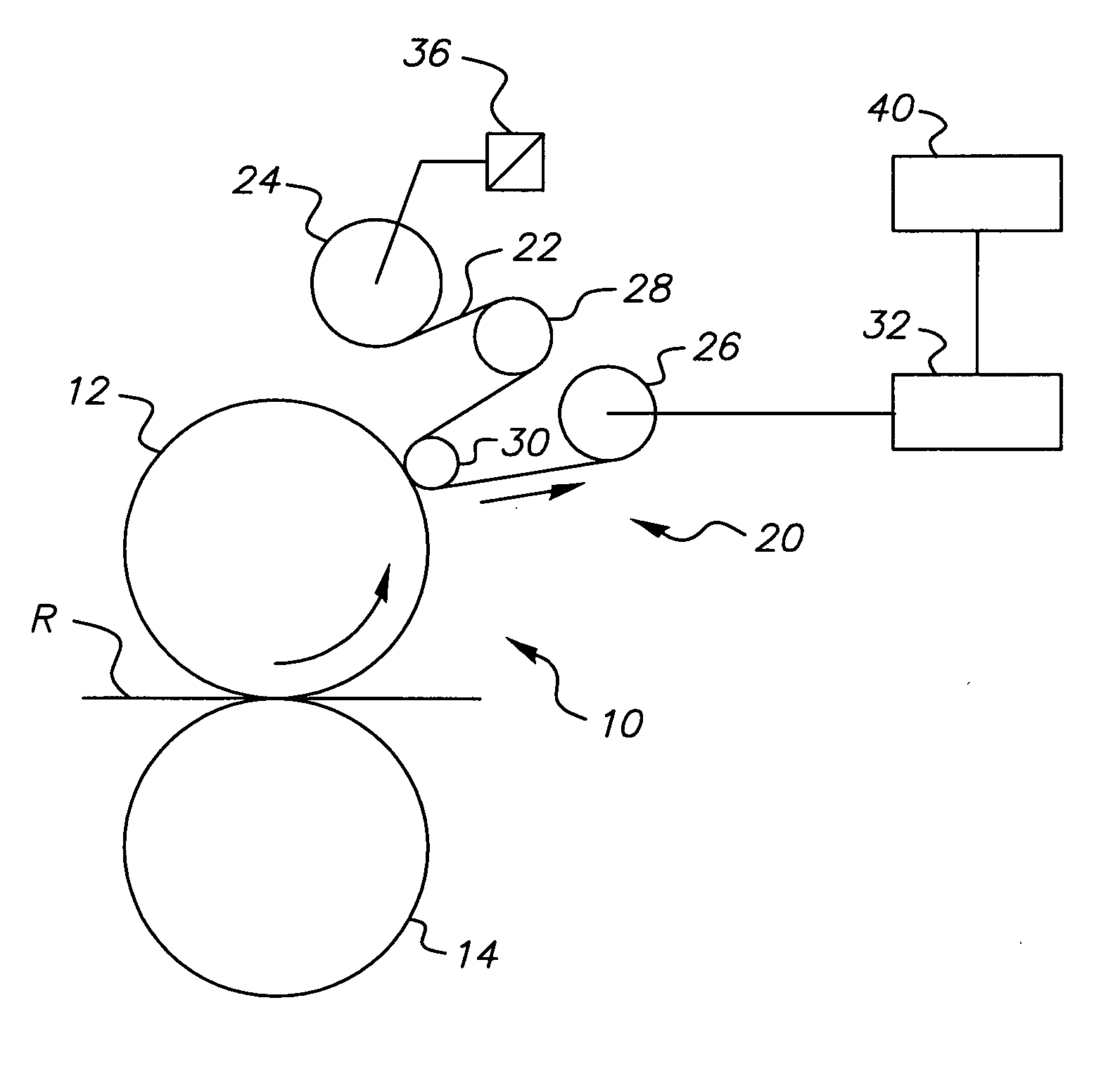
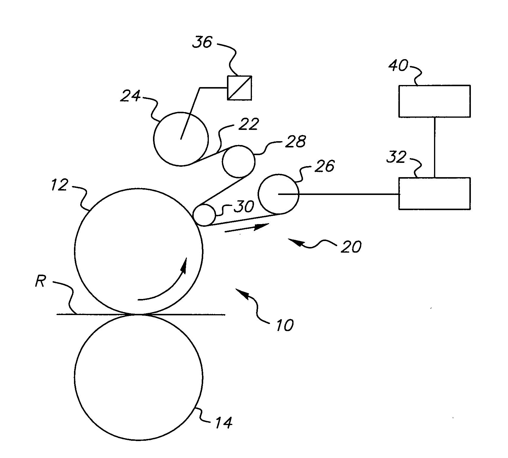
[0010] Referring to the FIGURE, there is schematically shown various components of an electrostatographic reproduction apparatus fuser assembly, including release oil impregnated web oiler mechanism, the linear velocity of which may be maintained by this invention. The fuser assembly, designated generally by the numeral 10, has a fusing member 12 in the form of a roller, although a belt, sleeve, or any other variation thereof would be similarly applicable. The fusing member 12 is heated, and is located in nip relation with a pressure roller 14. The fusing nip between the roller of the fusing roller 12 and pressure roller 14 is associated with the receiver member transport path of the reproduction apparatus. That is, as a receiver member bearing a marking particle image travels along the transport path, the marking particle image is fixed to the receiver member by application of heat and pressure in the fusing nip before the receiver member is delivered from the transport path to an ...


PUM


Abstract

Maintaining the linear velocity of an oil impregnated web oiler as the oil impregnated web is wound onto a driven take-up roll. When a new oil impregnated web is installed, the take-up roll is initially driven at an angular velocity to yield the predetermined optimum linear velocity of the oil impregnated web. The angular velocity of the take-up roll is decreased according to the algorithm of the invention so as to maintain constant the linear velocity of the oil impregnated web as the oil impregnated web is wound onto the take-up roll.

Description

FIELD OF THE INVENTION [0001] This invention relates in general to release fluid applicators for heated fuser rollers and more particularly to a method of controlling the linear speed of a release fluid, oil impregnated, web oiler. BACKGROUND OF THE INVENTION [0002] In electrostatographic reproduction apparatus a latent image charge pattern is formed on a uniformly charged charge-retentive or photoconductive member having dielectric characteristics. Pigmented marking particles are attracted to the latent image charge pattern to develop such image on the photoconductive member. A receiver member, such as a sheet of paper, transparency or other medium, is then brought into contact with the photoconductive member, and an electric field applied to transfer the marking particle developed image to the receiver member from the photoconductive member. After transfer, the receiver member bearing the transferred image is transported away from the photoconductive member, and the image is fixed...

Claims


Application Information

Patent Timeline
Patent Type & Authority Applications(United States)
IPC IPC(8): G03G15/20
CPCG03G2215/2093G03G15/2025
Inventor BERG, RICHARD H.WU, FANGSHENG
Owner EASTMAN KODAK CO
Why Eureka
Try Eureka