
Image capturing apparatus

Active Publication Date: 2019-02-28
CANON KK
View PDF5 Cites 7 Cited by
  • Summary
  • Abstract
  • Description
  • Claims
  • Application Information

AI Technical Summary

Benefits of technology

The present invention is a multi-lens camera system that can capture video images even when the position of the camera changes. It includes multiple imaging units and illumination units that move in a circular manner. The imaging and illumination units move together, ensuring that they align with each other. This allows for a good video image to be obtained.

Problems solved by technology

However, an obstacle, such as a wall, may be present near the multi-lens camera apparatus depending on an installation location.

Method used


Image

  • Image capturing apparatus
  • Image capturing apparatus
  • Image capturing apparatus

Examples


Embodiment Construction

[0017]Hereinafter, embodiments are described in detail with reference to the accompanying drawings. A description of a cable and a component which are not directly related to the embodiments is omitted, and the cable and the component are not illustrated in the drawings.

[0018]A first embodiment of the present invention will be described below in detail. In the present embodiment, a multi-lens camera apparatus 1 will be described.

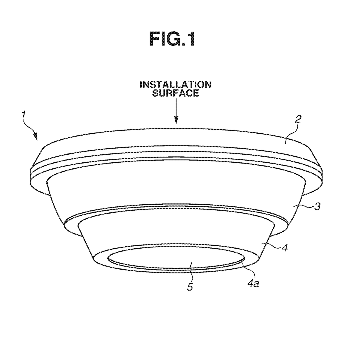
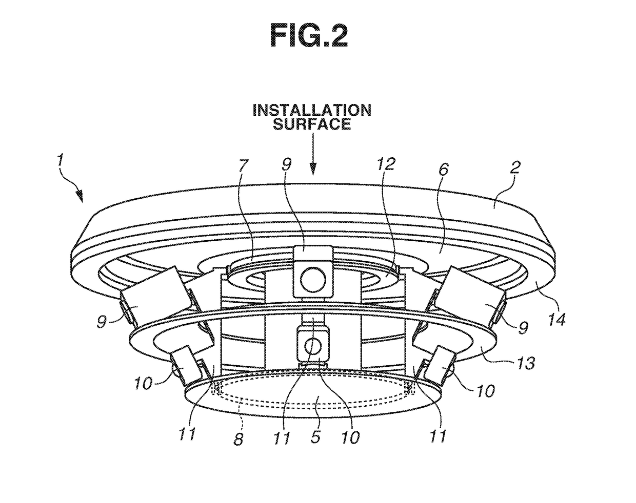
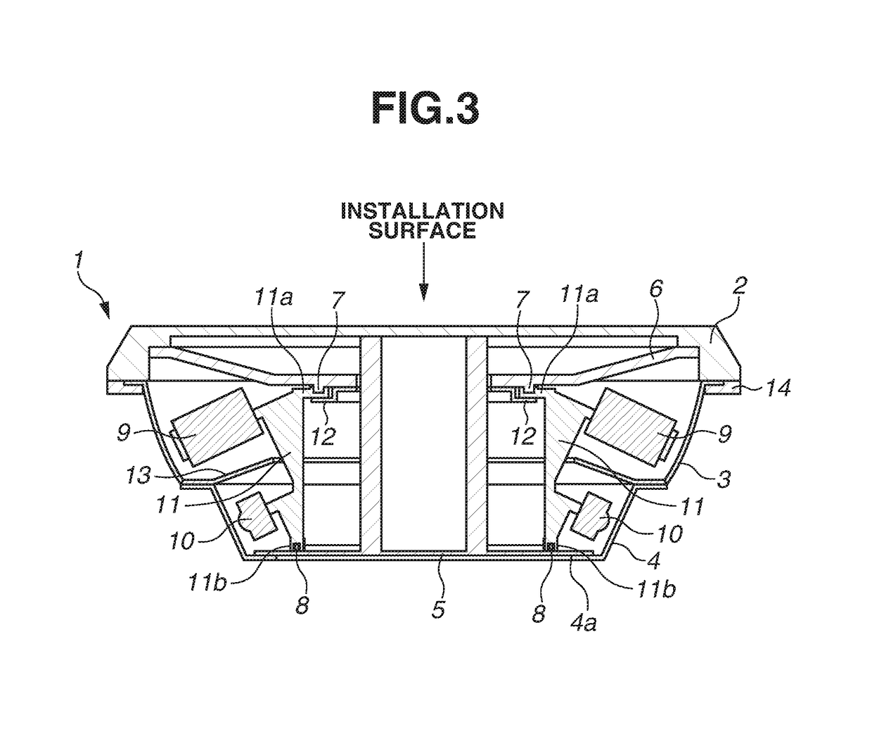
[0019]FIG. 1 is a perspective view of the multi-lens camera apparatus 1 according to the present embodiment. FIG. 2 is a perspective view of the multi-lens camera apparatus without a visible light transmission window 3 and an illumination light transmission window 4. FIG. 3 is a sectional view of the multi-lens camera apparatus 1.

[0020]The multi-lens camera apparatus 1 includes a top case 2, the visible light transmission window 3, the illumination light transmission window 4, a bottom cover 5, a plurality of imaging units 9, a plurality of illumination unit...


PUM


Abstract

An image capturing apparatus includes a plurality of imaging units arranged in a circumferential manner and movable in a circumferential direction, and a plurality of illumination units arranged in such a manner that each of the plurality of illumination units corresponds to a different one of the plurality of imaging units. In a case where the plurality of imaging units moves in the circumferential direction, each of the plurality of imaging units integrally moves with a corresponding one of the plurality of illumination units.

Description

BACKGROUND OF THE INVENTIONField of the invention[0001]The present invention relates to an image capturing apparatus, and more particularly to an image capturing apparatus including a plurality of imaging units arranged in a circumferential manner.Description of the Related Art[0002]There are multi-lens camera apparatuses capable of capturing large area images. Such a multi-lens camera apparatus is provided with plurality of imaging units arranged in a circumferential manner. In some cases, for example, a multi-lens camera apparatus includes a plurality of imaging units that is fixed so that a visual field of 360 degrees can be captured. However, an obstacle, such as a wall, may be present near the multi-lens camera apparatus depending on an installation location. In such a case, an imaging range of at east one of the imaging units may be blocked by the obstacle. Thus, a position of the imaging unit is desirably changeable at will. Japanese Patent Application Laid-Open No. 2015-1194...

Claims


Application Information

Patent Timeline
IPC IPC(8): H04N5/247H04N5/225H04N5/232
CPCH04N5/247H04N5/2256H04N5/23296H04N5/2253H04N23/56H04N23/51H04N23/50H04N23/55H04N23/90H04N23/45H04N23/74H04N23/54H04N23/69
Inventor YASUTAKE, YUTATAKAHATA, KAZUMA
Owner CANON KK
Features
  • Generate Ideas
  • Intellectual Property
  • Life Sciences
  • Materials
  • Tech Scout
  • Unparalleled Data Quality
  • Higher Quality Content
  • 60% Fewer Hallucinations
Learn More