Curve determination method, device and equipment

A technology to determine the method and curve, which is applied in the field of image processing, can solve the problems that the zoom follow curve cannot be applied to cameras, poor image clarity, and unclear images, etc., and achieve rapid calibration of the zoom follow curve, solve the problem of unsmooth and image effects Good results

Pending Publication Date: 2022-03-25
HANGZHOU HIKVISION DIGITAL TECH
4 Cites 0 Cited by

AI-Extracted Technical Summary

Problems solved by technology

[0005] In related technologies, the zoom follow curve is configured based on user experience, and all cameras are configured with the same zoom follow curve. However, due to differences in the lenses of different cameras, the zoom follow curve cannot be applied to all cameras. The image collected by following the curve is not clear and the image effect is...

Method used

Referring to shown in Fig. 4 C, be the schematic diagram of polynomial curve fitting, because 5 order polynomials can fit curve well, in the process that curve is determined, can reduce calibration point to 9, therefore, in the present embodiment In , the positive zoom follow curve can be calculated by the 5th order polynomial curve fitting method to achieve the purpose of fast calibration. When polynomial curve fitting is performed using a 5th-order polynomial, the number Q of coordinate points (ie, calibration points) may be nine. Of course, the 5th-order polynomial and 9 coordinate points are just examples, and there is no limit to this.
Visible by above technical scheme, in the embodiment of the application, construct P coordinate points, coordinate point comprises the distance value corresponding to the 3rd position point and the distance value corresponding to the 4th position point matching with this 3rd position point, When the zoom lens is at the third position point and the focus lens is at the fourth position point, the image collected by the camera is relatively clear and meets the definition requirement. After performing polynomial curve fitting on the P coordinate points, a reverse zoom is obtained After following the curve, the image collected based on the reverse zoom following the curve is clearer and the image effect is better. For different cameras, determine the third position point and the fourth position point based on the images collected by the camera, that is, determine the reverse zoom follow curve for the camera based on the images collected by the camera, that is, different cameras can correspond to different reverse zoom follow curve, so that the reverse zoom follow curve can be applied to this camera. The reverse zoom follow curve can be determined by polynomial curve f...

Abstract

The invention provides a curve determination method, device and equipment. The method comprises the following steps: controlling a zoom lens to move to Q first position points through a zoom motor; controlling a zoom lens to stop at a first position point through a zoom motor, and controlling a focusing lens to move to a second position point matched with the first position point through a focusing motor; wherein when the focusing lens moves to the second position point, the image acquired by the camera meets the definition requirement; constructing Q coordinate points based on the Q first position points and the Q second position points; performing polynomial curve fitting on the Q coordinate points to obtain a forward zoom following curve; the forward zoom following curve represents the mapping relation between the position point of the zoom lens and the position point of the focusing lens. According to the technical scheme, the image acquired based on the zoom following curve is clear, and the image effect is good.

Application Domain

Technology Topic

OphthalmologyZoom lens +2

Image

  • Curve determination method, device and equipment
  • Curve determination method, device and equipment
  • Curve determination method, device and equipment

Examples

  • Experimental program(1)

Example Embodiment

[0024] The terminology used in the present application embodiment is merely the purpose of describing particular embodiments, and not limiting the present application. The "one", "one", "one", "one", "one" and "" "used in the claims and the claims are also intended to include most forms unless the context clearly represents other meaning. It should also be understood that the terms "and / or" as used herein refer to any or from any or all possible combinations of one or more associated listing items.
[0025] It should be understood that although the terms first, second, third, etc., the terms first, second, and third, etc. may be described in the present application, but this information should not be limited to these terms. These terms are used only to distinguish the same type of information from each other. For example, the first information may be referred to as a second information without departing from the scope of the present application, and the second information can also be referred to as the first information. Depending on the context, in addition, the words used "If" can be interpreted as "in ..." or "when ..." or "in response to determination".
[0026] In the present application, a curve determination method can be applied to the camera, the camera can include a zoom motor, a focus motor, a zoom lens, and a focus lens, a zoom motor for controlling the zoom lens in the first endpoint and the second The endpoint moves (i.e., the zoom lens moves in a direction from the first end point to the second endpoint, or the zoom lens moves in a direction from the second end point to the first end point), the focus motor is used to control the focus lens in the first One end point moves between the second endpoint (ie the focusing lens moves in a direction from the first end point to the second end point, or moving in a direction from the second end point to the first endpoint). Exemplary, the first endpoint is the smaller end of the camera, that is, the W-terminal (Wide) of the camera, the second end point is the camera's lens focal length, that is, the TELEDE of the camera.
[0027] When moving from the first end point to the second endpoint, the lens focal length of the camera gradually becomes large, and when moving from the second end point to the first end point, the camera focal length is gradually smaller. For example, when the zoom lens moves in a direction from the first end point to the second endpoint, the focal length of the zoom lens gradually becomes large, and when the zoom lens moves in the direction of the second end point to the first end point, the focal length of the zoom lens gradually changes. Small. When the focus lens moves from the first end point to the second endpoint, the focus lens is gradually large, and when the focus lens is moved from the second end point to the first end point, the focusing lens is gradually smaller.
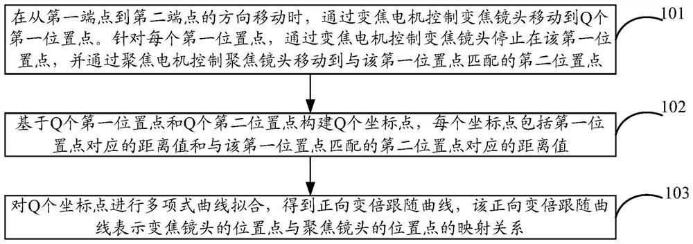
[0028] See figure 1 As shown, a flow diagram of a method of determining a method, which may include:
[0029] Step 101, when moving from the first end point to the second end point, the zoom lens is moved to the Q first position by the zoom motor control. For each first position point, the zoom lens is stopped by the zoom motor control, and the focus lens is moved to the second position point that matches the first position point by the focus motor. Exemplary, when the focus lens moves to a second position point matches the first position point, the image acquired by the camera satisfies the sharpness requirements, that is, the image sharpness is relatively high.
[0030] In a possible embodiment, for step 101, the focusing lens is moved to the second position point that matches the first position point by the focus motor, which may include, but not limited to, as follows:
[0031] Way 1, by the focusing motor controls the focus lens to move to a position point, and control the focus lens to stop at this location point, collect images through the camera. If the sharpness of the image is larger than the sharpness threshold (indicating that the image satisfies the sharpness requirements), the location point can be determined as the second position point that matches the first position point. If the sharpness of the image is not larger than the sharpness threshold, continue by the focus motor to control the focus lens to another location point, so that the sharpness of the image collected by the camera is greater than the sharpness threshold, resulting in the first A second location point matching a location point.
[0032] Way 2, by focusing the motor controls the focus lens to move to a plurality of position points; for each position point, the control focus lens stops at this position point, collecting the position corresponding to the location point by the camera. On this basis, the maximum sharpness can be determined based on the sharpness of the image corresponding to all position points, and the position point corresponding to the maximum sharpness is determined to match the second position point that matches the first position point.
[0033] Step 102, based on the Q first position points and Q second position points, the Q coordinate points are constructed, and each coordinate point includes a distance value corresponding to the first position point and a second position point matching the first position point. Distance value. For example, the coordinate point 1 includes a distance value corresponding to the first position point A1 and the distance value corresponding to the second position point B1 that matches the first position point A1, and the coordinate point 2 includes a distance value corresponding to the first position point A2 and The first position point A2 matches the second position point B2 corresponding to the distance value, in this type.
[0034] Exemplary, based on q first position points and Q second position points, the Q coordinate points include, but are not limited to, the distance between the first position point and the first end point as the abscissa, will The distance value of the second position point matches the first position point as the ordinate, generates a coordinate point; or the distance value between the first position point and the first end point as the ordinate, The distance value between the second position point matches the first position point and the first end point generates a coordinate point.
[0035] For example, the coordinate system is established, and the coordinate system is horizontally right as horizontal axis, and it is vertically upward, and of course, it can also be used to establish coordinate systems in other ways, which is not limited. The coordinate point 1 is (x1, y1), X1 represents the distance value between the first position point A1 and the first end point, and X1 is used as the abscissa, and Y1 represents the distance between the second position point B1 and the first end point. Value, and Y1 as the ordinate. The coordinate point 2 is (x2, y2), x2 represents the distance value between the first position point A2 and the first end point, and X2 is used as the abscissa, and Y2 represents the distance between the second position point B2 and the first end point. Value, and Y2 as a longitudinal coordinate, in this type.
[0036] Step 103, a polynomial curve is fitted to the Q coordinate point to obtain a forward variational follow-up curve, the forward variation, follow the curve representation of the position point of the zoom lens and the location point of the focus lens.
[0037] For example, the K-order polynomial can be used to fit the Q coordinate points to obtain a forward variation and follow shape. Exemplary, K is greater than or equal to 2, Q is greater than or equal to 3. For example, the K step polynomial can be 5-order polynomial, and Q coordinate points can be 9 coordinate points.
[0038] Of course, the value of the above K is only an example, which does not limit this, as long as k is greater than or equal to 2. The value of the above Q is only an example, which does not limit this, as long as the q is greater than or equal to 3.
[0039] In a possible embodiment, after the forward variation is followed by the curve, during the actual operation of the camera, that is, the camera collects the image, the correction can be used to follow the curve according to the forward variation, in order to Implementation variation, can be used as follows: When moving from the first end point to the second endpoint, if the zoom lens is moved to the initial position by the zoom motor control, it follows the curve by querying the forward variation. The initial position point corresponds to the target location point, and moving the focus lens via the focus motor to move to the target position point. When the zoom lens moves to the initial position, and the focus lens is moved to the target position point, the image is collected by the camera, which is relatively high.
[0040] As can be seen from the above, in the present embodiment, the Q coordinate points are constructed, and the coordinate point includes a distance value corresponding to the first position point and a distance value corresponding to the second position point matching the first position point, in the zoom lens When the first position point, and the focus lens is in the second position point, the image capture of the camera is relatively clear, satisfying the sharpness requirements, fitting a polynomial curve for q coordinate points, and obtaining a forward variational follow-up curve, The image based on the forward variation and follow the curve is relatively clear, and the image effect is better. For different cameras, the image is determined based on the image acquisition point, that is, the image acquired by the camera is determined to determine the forward variational follow-up curve for the camera, that is, the different cameras can correspond to different forward variations. The curve makes the forward variational follow-up curve can be applied to the camera. It can be determined by the polynomial curve to determine the forward variational follow-up curve, and can be close to the actual curve, effectively solve the problem of changing the uncomidity of the curve, reaching the image clear effect, can significantly reduce the number of sample points (ie the number of coordinate points) Less) to achieve the purpose of rapid calibration forward variation and follow the curve.
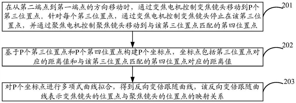
[0041] See figure 2 As shown, a flow diagram of a method of determining a method, which may include:
[0042] Step 201, when moving from the second end point to the first endpoint, the zoom lens is moved to the P third position point by the zoom motor control. For each third bit point, the zoom lens is stopped at the third position point by the zoom motor control, and the focusing lens is moved to the fourth position point that matches the third position point by the focus motor. Exemplary, when the focus lens moves to the fourth position point matching the third position point, the image acquisition of the image satisfies the sharpness requirements, that is, the image sharpness is relatively high.
[0043] In one possible embodiment, for step 201, the focusing lens is moved to the fourth position point that matches the third position point by the focus motor, which may include, but are not limited to, as follows:
[0044] Way 1, by the focusing motor controls the focus lens to move to a position point, and control the focus lens to stop at this location point, collect images through the camera. If the sharpness of the image is larger than the sharpness threshold (indicating that the image satisfies the sharpness requirements), the location point can be determined to match the fourth position point matching the third position point. If the sharpness of the image is not larger than the sharpness threshold, continue by the focus motor to control the focus lens to another location point, so that the sharpness of the image collected by the camera is greater than the sharpness threshold, resulting in the first The fourth location point matching the three-position point.
[0045] Way 2, by focusing the motor controls the focus lens to move to a plurality of position points; for each position point, the control focus lens stops at this position point, collecting the position corresponding to the location point by the camera. On this basis, the maximum definition can be determined based on the sharpness of the image corresponding to all position points, and the position point corresponding to the maximum sharpness is determined to match the fourth position point matching the third position point.
[0046] Step 202, based on the P third position points and the P fourth position points, the coordinate point includes the distance value corresponding to the third position point and the distance corresponding to the fourth position point matching the third position point. value.
[0047] Exemplary, based on P third position points and P fourth position points, a P-coordinate point includes, but is not limited to, the distance value between the third position point and the first end point will be used as a horizontal coordinate. The distance value between the fourth position point matches the first end point as the ordinate, generates a coordinate point; or the distance value between the third position point and the first end point as the ordinate, The distance value between the fourth position point matching the third position point and the first end point generates a coordinate point.
[0048] Step 203, a polynomial curve is fitted to the P coordinate point, resulting in a reverse variational follow-up curve, the reverse variation with the curve representation of the position point of the zoom lens and the location point of the focus lens.
[0049] For example, a C-order polynomial can be used to fit a polynomial curve to a reverse variational follow-up curve. Exemplary, K is greater than or equal to 2, P is greater than or equal to 3. For example, the K step polynomial can be 5-order polynomial, and the P coordinate points can be 9 coordinate points.
[0050] Of course, the value of the above K is only an example, which does not limit this, as long as k is greater than or equal to 2. The value of the above P is only an example, which does not limit this, as long as P is greater than or equal to 3.
[0051] In a possible embodiment, after the reverse variational follow-up curve is obtained, during the actual operation of the camera, that is, the camera collects the image, it can be based on the reverse variation with the curve to achieve the magnification, in order to Implementation, can be used as follows: When moving from the second end point to the first endpoint, if the zoom lens is moved to the initial position point by the zoom motor control, it follows the curve by querying the reverse variation. The initial position point corresponds to the target location point, and moving the focus lens via the focus motor to move to the target position point. When the zoom lens moves to the initial position, and the focus lens is moved to the target position point, the image is collected by the camera, which is relatively high.
[0052] As can be seen from the above technical solution, in the present application, a P coordinate point is constructed, and the coordinate point includes a distance value corresponding to the third position point and a distance value corresponding to the fourth position point matching the third position point, in the zoom lens. At the third position point, and when the focusing lens is in the fourth position point, the image capture of the camera is relatively clear, satisfying the sharpness requirements, fitting a polynomial curve to the P coordinate point, and obtaining the reverse variational follow-up curve. , Based on reverse variation, follow the curve collected, the image is clearer, and the image effect is better. For different cameras, based on the image acquired image, the third position point and the fourth position point are determined based on the image acquired by the camera, that is, the different cameras can correspond to different reverse variations. The curve makes the reverse variational follow-up curve can be applied to the camera. It can be assigned to determine the reverse variational follow-up curve by polynomial curve, and can be close to the actual curve, effectively solve the problem of changing the curve of the curve, achieving the image clear effect, can significantly reduce the number of sample points (ie the number of coordinate points) Less) to achieve the purpose of rapid calibration reverse variational follow-up curve.
[0053] The above technical scheme of the present application will be described below with reference to the specific application scenario.
[0054] Camera typically requires zoom (also known as a variation) function and focus (also known as a focus or focus) function. The zoom function refers to adjusting the distance from the scene, that is, the zoom function changes the sputum, used to control the angle of view. The focus function refers to the sharpness of the adjustment screen, that is, the focus function changes the focal length for controlling the sharpness. In order to achieve the zoom function and focus function at the same time, the camera can include a zoom motor (also referred to as a ZOOM motor), the focus motor (also referred to as an FOCUS motor), the zoom lens (also referred to as a post lens) and the focus lens (also A front lens), drive the zoom lens through the zoom motor to achieve the zoom function, drive the focus lens by the focus motor to achieve the focus function.
[0055] The camera typically has a W-terminal (Wide) and T-terminal (the W end is the lens focal length of the camera), that is, the first end point of the above embodiment), and the T terminal is the lens focal length of the camera (ie the above). The second endpoint of the embodiment). In the direction from the W end to T, the lens focal length gradually becomes large, and in the direction from the T end to the W end, the lens focal length gradually becomes small. In summary, the W end is the location point where the camera's lens is the smallest position, and the T end is the maximum position point of the camera's lens focal length.
[0056] Since the camera includes two separate lenses such as zoom lens and focusing lenses, the zoom lens needs to correspond to the W end and T terminal, and the focus lens also needs to correspond to the W end and T end, in order to distinguish, the zoom lens can be used. Terminal is W1, and the T terminal of the zoom lens is T1, and the W terminal of the focus lens can be written as W2, and the T terminal of the focus lens is T2 end.
[0057]The zoom lens moves between the W1 end and the T1 end, that is, the zoom lens moves from the W1 end to the T1 or from the T1 end to the W1 end. When the zoom lens is moved from the W1 to the T1, the focal length of the zoom lens gradually becomes large, and when the zoom lens moves from the T1 to the W1 end, the focal length of the zoom lens gradually becomes small.
[0058] The focus lens moves between the W2 end and the T2 end, that is, the focusing lens moves from the W2 end to the T2 end, or moves from the T2 end to the W2 end. When the focus lens moves from the W2 to the T2 terminal, the focus lens gradually becomes large, and when the focus lens moves from the T2 end to the W2 end, the focusing lens gradually becomes small.
[0059] Exemplary, in the process of moving from the W1 end to the T1 end, the focusing lens is moving from the W2 end to the T2 terminal, that is, during the process of moving from the W1 end through the zoom motor drive zoom lens, pass The focus motor drives the focus lens to move from the W2 end to the T2 end to achieve a variation. During the zoom lens moves from the T1 end to the W1 end, the focus lens is moved from the T2 end to the W2 terminal, that is, during the process of moving from the T1 end through the zoom motor drive zoom lens, by the focus motor drives the focus The lens moves from the T2 end to the W2 end to achieve the transformation.
[0060] In order to achieve a variation, it is usually necessary to obtain a variational follow-up curve, which may include a map of the zoom lens and the location point of the focus lens. Among them, the positional point of the zoom lens represents the distance value between the current position point of the zoom lens and the W1 end of the zoom lens, and the position point of the focus lens represents the distance value between the current position points of the focus lens and the W2 end of the focus lens.
[0061] In order to obtain a variational follow-up curve (this embodiment will divide the magnitude of the curve into the forward variational follow-up curve and the reverse variational follow-up curve, the forward variational follow-up curve is a variation of the corresponding to the W end to the T-terminal direction. The curve, the reverse variational follow-up curve is a variational follow-up curve corresponding to the T end to the W-terminal direction), and a curve determination method is proposed in the present application, the method can be applied to the camera, the camera can include a zoom motor, Focus motor, zoom lens and focus lens. Among them, the zoom motor is used to control the zoom lens between the W1 end and the T1 end (i.e., the zoom lens moves from the W1 end to the T1 end, or moving from the T1 end to the W1 end), the focus motor is used to control the focus lens in W2 Move between ends and T2 ends (ie, the focusing lens moves from the W2 end to the T2 end, or moving from the T2 end to the W2 end).
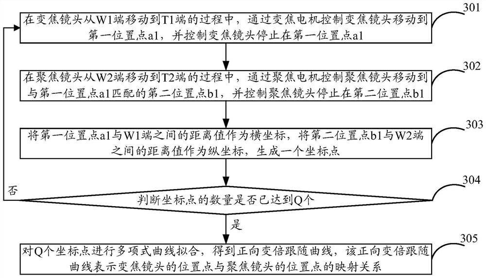
[0062] In order to get the forward variation, see the curve, see image 3 As shown, a curve determination method is proposed in the present application, which can be applied to a camera, which may include the following steps:
[0063] In step 301, during the convex ratio from the W1 end to the T1 end, the zoom motor controls the zoom lens to the first position point A1, and the zoom lens stops in the first position point A1.
[0064] Step 302, during the frequency of the focus lens from the W2 end to the T2 end, by the focus motor controls the focus lens to the second position point B1 that matches the first position point A1, and control the focus lens to stop in the second position B1. Exemplary, when the focus lens moves to the second position B1 that matches the first position point A1, the image acquisition of the camera satisfies the sharpness requirements, that is, the image sharpness is relatively high.
[0065] In order to find the second location B1 that matches the first position point A1, it can be used as follows:
[0066] Ways 1, all position points between the W2 ends to the T2 end can be divided into M position points, such as the distance value between the two position points, such as the distance between the adjacent position points. 0.1 cm, etc., the division is not limited. On this basis, the focusing motor can be moved to the first position point by the focusing motor, and the control focus lens is stopped at the first position point and collects images by the camera.
[0067] Then, determine the sharpness of the image, the determination method is not limited. After obtaining the sharpness of the image, if the sharpness of the image is larger than the sharpness threshold (can be configured according to the empirical configuration), the first position point can be used as the first position point A1. Two positions B1.
[0068] If the sharpness of the image is not more than the sharpness threshold, the control focusing lens is moved to the second position by the focusing motor, and the control focus lens stops at the second position point and collects images through the camera.
[0069] Then, the sharpness of the image is determined, and if the sharpness of the image is larger than the sharpness threshold, the second position point can be used as the second position point B1 that matches the first position point A1.
[0070] If the sharpness of the image is not more than the sharpness threshold, the focusing motor is controlled to the third position point, and the control focus lens stops in the third position point and collects images by the camera.
[0071] In this kind, the sharpness of the image acquired by the image acquired by the camera is greater than the definition threshold, and the second position point B1 that matches the first position point A1 is obtained, and the second position point B1 is obtained.
[0072] Method 2, all position points between the W2 ends to the T2 end can be divided into m position points, such as the distance value between the adjacent positions, such as the distance value between the adjacent position points. 0.1 cm, etc., the division is not limited. On this basis, the focusing motor can be moved to the first position point by the focusing motor, and the control focus lens is stopped at the first position point, and the image corresponding to the first position point is collected by the camera, and determines the clearness of the image. Spend. Then, by the focusing motor controls the focus lens to move to the second position point, the control focus lens stops at the second position point, and collects the image corresponding to the second position point by the camera, and determines the sharpness of the image. In this kind, the focusing motor is moved to the mth position point by controlling the focus lens by the focus motor, and the control focus lens stops at the mth position point, and collects the image corresponding to the mth position point by the camera, and determines the clearness of the image. Spend.
[0073] In summary, the sharpness of the M images can be obtained. On this basis, the maximum sharpness can be determined from all images, and the position point corresponding to the maximum sharpness is matched as the first position point A1. The second location point B1. For example, if the clarity of the image corresponding to the third position point is the largest, the third position point is the second position point B1 that matches the first position point A1.
[0074] Of course, the above mode is only two examples, and the image clarity is relatively high as long as the second position point B1 can be obtained, and the focus lens moves to the second position point B1.
[0075] Step 303, the distance value between the first position points A1 and the W1 end as the horizontal coordinate, generates a coordinate point between the distance value between the second position points B1 and the W2 end.
[0076] See Figure 4A As shown, a coordinate system can be created, the coordinate system is horizontally right as the horizontal axis, which is vertically upward, based on this, the coordinate point may be (x1, y1), X1 represents the first position point A1 and W1 The distance value between the ends, Y1 represents the distance value between the second position points B1 and the W2 end.
[0077] Among them, in order to determine the distance value between the first position points A1 and the W1 end, the following method can be employed:
[0078] The initial angle of the zoom motor and the initial position (ie, W1 end) of the zoom lens, when the zoom motor starts to rotate from the initial angle, the zoom lens will start moving from the W1 end, moving to the first position point A1 in the control zoom lens When it is determined to determine the target angle of the zoom motor, determine the rotational angle z1 between the target angle and the initial angle (ie the difference between the target angle and the initial angle), that is, the zoom motor rotates the angle Z1, the zoom lens moves the distance of X1. value. On this basis, the distance value X1 between the first position points A1 and the W1 end can be calculated based on the rotational angle Z1. For example, the rotational angle is a mapping relationship with the moving distance value, and when the zoom motor rotates 1 degree, the zoom lens moves 0.1 cm, based on the mapping relationship, the distance value X1 can be calculated based on the rotation angle Z1, such as the rotation angle z1 is 3 Degree, the distance value x1 is 0.3 cm and the rotational angle z1 is 5 degrees, and the distance value x1 is 0.5 cm, and it is pushed.
[0079] Among them, in order to determine the distance value between the second position points B1 and the W2 end, it can be used as follows:
[0080] The initial angle of the focus motor (i.e., W2 end) of the focusing lens, when the focus motor begins to rotate from the initial angle, the focus lens will start moving from the W2 end, in the control focus lens to move to the second location point B1 When determining the target angle of the focus motor, determine the rotational angle z2 between the target angle and the initial angle (ie the difference between the target angle and the initial angle), that is, the focus motor rotates the angle Z2, the focus lens moves the distance of Y1. value. On this basis, the distance value Y1 between the second position points and the W2 end can be calculated based on the rotation angle Z2. For example, the rotational angle is a mapping relationship with the moving distance value. When the focus motor is rotated 1 degree, the focus lens moves 0.1 cm, based on the mapping relationship, the distance value Y1 can be calculated based on the rotation angle Z2, such as the rotation angle z2 is 2 Degree, the distance value Y1 is 0.2 cm, the rotation angle z2 is 4 degrees, and the distance value Y1 is 0.4 cm, and so on.
[0081] In summary, the distance value Y1 between the distance value X1 and the W1 end between the first position points A1 and the W1 end can be calculated, and a coordinate point (X1, Y1) is generated.
[0082] Step 304, determine if the number of coordinate points has reached Q, and if so, step 305 can be performed. If no, then you can return to step 301, i.e., step 301-step 304 is repeated.
[0083] Exemplary, q may be greater than or equal to 3, the value of this Q is not limited, as long as it is greater than or equal to 3, such as Q is 5, 7, 9, etc. For convenience, Q is 9 as an example. .
[0084] When step 301-step 304 is performed for the first time, the zoom lens moves to the first position point A2, the focus lens moves to the second position point B2, and generates the coordinate point (X2, Y2), X2 represents the first position point A2 The distance value between the W1 end, Y2 represents the distance value between the second position point B2 and the W2 end.
[0085] When step 301-step 304 is repeated in the second time, the zoom lens moves to the first position point A3, the focus lens moves to the second position point B3, and generates a coordinate point (X3, Y3), X3 represents the first position point A3. The distance value between the W1 end indicates the distance value between the second position point B3 and the W2 end.
[0086] With this type, you can eventually get 9 (ie Q) coordinate points, see Figure 4b Indicated.
[0087] Step 305, a polynomial curve is fitted to the q coordinate point to obtain a forward variational follow-up curve, which is a mapping relationship between the position point of the zoom lens represents the position point of the zoom lens.
[0088] For example, the K-order polynomial can be used to fit the Q coordinate points to obtain a forward variation and follow shape. Exemplary, K may be greater than or equal to 2, Q may be greater than or equal to 3. For example, the K step polynomial can be 5-order polynomial, and Q coordinate points can be 9 coordinate points. Of course, the value of the above K is only an example, which does not limit this, as long as k is greater than or equal to 2.
[0089]The following combination of the specific application scenario is combined, the K - order polynomial curve fitting process will be described.
[0090] See Figure 4C As shown in the schematic of the polynomial curve fitting, since the 5-order polynomial can fit the curve, the calibration point to 9 can be reduced during the curve determination, and therefore, in the present embodiment, the 5th order can be passed. Multi-class fitting curve calculates the forward variational follow-up curve to achieve the purpose of rapid calibration. When a polynomial curve is fitted with a 5-order polynomial, the number Q of the coordinate point (ie, the calibration point) can be 9. Of course, the 5th-order polynomial and 9 coordinate points are just examples, which do not limit this.
[0091] Suppose 9 coordinate points, these coordinate points are recorded (X 1 , X 1 ), (X 2 , X 2 ), ... (x n Y n The value of n is 9, and when the K-order polynomial fitting, the K-order multiplicity function see the formula (1):
[0092] f (x) = a 0 + a 1 * x + a 2 * x 2 + ... + a k * x k Formula 1)
[0093] If all the coordinate points are substituting into the formula (1), you can get the following n-group equation:
[0094]
[0095] The above-mentioned non-aliquot is not necessarily a solution, that is, the coordinate point cannot be fitted under the K-order multiplicity curve, so it is necessary to find the minimum difference between Y and real Y between the polynomial calculated to achieve the same as possible A coordinate point, such as, the least squares method shown in Equation (2) can be used.
[0096]
[0097] Then, by substituting the formula (1) into the formula (2), it can be obtained (3):
[0098]
[0099] When calculating the minimum of formula (3), it can be passed to A 0 , A 1 , ... a k If you want to make it 0, you can solve all the value of all A (ie a 0 , A 1 , ... a k The value of the value is obtained, so as to get the following:
[0100]
[0101] Further, by organizing the above equation, it can be obtained as follows:
[0102]
[0103]
[0104] Further, the above-mentioned bonus is changed into a matrix method, which can be obtained as follows (4):
[0105]
[0106] Then, suppose So, the formula (4) continues to decompose, you can get the following formula: X T XA = X T Y, after deformation of the above formula, you can get: a = (t X X) - 1 X T Y. In the above formula, X and Y are known, based on the above 9 coordinate points (eg (X) 1 Y 1 ), (X 2 Y 2 ), ... (x n Y n ), Etc., obviously, based on formula A = (x T X) -1 X T Y can get a value of A, that is, you can get A 0 , A 1 , A 2 , ..., A k Value.
[0107] Exemplary, in the 5-order polynomial fitting polynomial fitting, get A when the forward variation is followed by the curve, can get A 0 , A 1 , A 2 , A 3 , A 4 , A 5 Value, then, the above A 0 , A 1 , A 2 , A 3 , A 4 , A 5 The value is substituting into the formula (1), and a curve can be obtained. This curve is that the forward variation is followed by the formula (5), which is an example of the forward correction.
[0108] f (x) = a 0 + a 1 * x + a 2 * x 2 + ... + a 5 * x 5 Formula (5)
[0109] In summary, based on 9 coordinate points (X 1 Y 1 ), (X 2 Y 2 ), ... (x n Y n ), You can determine A 0 , A 1 , A 2 , A 3 , A 4 , A 5 The value is obtained, which will continue to obtain the forward variational follow-up curve shown in the formula (5).
[0110] In one possible embodiment, after the forward variation is followed by the forward variation, when the zoom lens moves from the W1 end to the T1 end, and the focusing lens moves from the W2 terminal to the T2 end, it is based on the forward variation. The curve is changed to the time, and it can ensure that the image captured by the camera is relatively clear. However, when the zoom lens moves from the T1 end to the W1 side, and the focusing lens moves from the T2 terminal to the W2 end, it is possible to change the image based on the forward variation and follow the curve, and the image cannot be guaranteed to be clear and why. The zoom lens has a backhaul difference (ie mechanical error), and the focus lens is a return time.
[0111] This return phenomenon can be construed as: when the zoom lens commutation (moving by the W1 end to the T1 end moves to the W1 end), the fact that there is a zoom motor running a few steps (such as 5 steps), but zoom lens There is no exercise, this is the return time of the zoom lens, which causes the coordinate deviation (ie, the zoom motor step and the moving distance of the zoom lens are deviated, and cannot be part corresponding). Similarly, when the focus lens is reversed (moving from the W2 terminal to the T2 end moves to the W2 end), the fact existed motor is running a few steps, but the focus lens has no exercise, this is the focus lens The backhaul is poor.
[0112] In order to eliminate the return time, you can get the reverse variational follow-up curve, when the zoom lens moves from the T1 end to the W1 end, and the focusing lens moves from the T2 terminal to the W2 end, based on the reverse variation, follow the curve, and Not based on forward variation, follow the curve, and ensure that the image captured by the camera is clear.
[0113] In order to obtain a reverse variation, see the curve, see Figure 5 As shown, a curve determination method is proposed in the present application, which can be applied to a camera, which may include the following steps:
[0114] In the process of moving the zoom motor to the W1 end, the zoom motor controls the zoom lens from the T1 end to the third position point, and the zoom lens stops in the third position point.
[0115] In the process of moving the focusing motor to the W2 end, the focusing motor is moved to the fourth position point that matches the third position point, and controls the focus lens to stop in the fourth position point. Exemplary, when the focus lens moves to a fourth position point matches the third position point, the image of the camera satisfies the sharpness requirements, that is, the image sharpness is relatively high.
[0116] Step 503, the distance value between the third position point and the W1 end, generates a coordinate point with the distance value between the fourth position point and the W2 end as the ordinate.
[0117] Exemplary, step 501-Step 503 can be seen in step 301-step 303, in which the zoom lens is moved from the T1 end to the W1 end in step 501-step 503, the focusing lens is moving from the T2 end to W2. In step 301-Step 303, the zoom lens is moved from the W1 end to the T1, the focusing lens is moving from the W2 end to the T2 end, and the implementation process is similar, and will be repeated here again.
[0118] Step 504, determine if the number of coordinate points has reached P, if yes, step 505 can be performed. If no, you can return to step 501, i.e., execute step 501-step 504.
[0119] Exemplary, P can be greater than or equal to 3, the value of this P is not limited, as long as it is greater than or equal to 3, such as 5, 7, 9, etc., for convenience, subsequent 9 as an example .
[0120] Exemplary, the value of P is the same, or may be different, the same as an example of both.
[0121] Step 505, a polynomial curve is fitted to the P coordinate point to obtain a reverse variational follow-up curve, which follows the curve to represent the position point of the zoom lens and the position point of the focus lens. For example, a C-order polynomial can be used to fit a polynomial curve to a reverse variational follow-up curve. Exemplary, K may be greater than or equal to 2, such as a 5-order polynomial, of course, the value of the K is only an example, which is not limited, as long as k is greater than or equal to 2.
[0122] Exemplary, step 505 can see Step 305 where it is no longer repeated.
[0123] In summary, it can be obtained to obtain a forward variation and follow curve and reverse variational follow-up curve, and the camera can store the forward variation and follow the curve and the reverse variational follow-up curve, during the actual operation of the camera. It can follow the curve based on the forward variation of the curve and the reverse variational follow-up curve, and the changing follows.
[0124]In one possible embodiment, for step 303, when generating a coordinate point, the distance value between the first position point and the W1 end can be used as the abscissa, the distance value between the second position point and the W2 end. As the ordinate, or, the distance value between the first position points and the T1 end may be used as the abscissa, and the distance value between the second position point and the T2 end can be used as the ordinate. In response to step 503, when the coordinate point is generated, the distance value between the third position point and the W1 end can be used as the abscissa, and the distance value between the fourth position point and the W2 end is used as the ordinate, or may The distance value between the third position point and the T1 side is used as the abscissa, and the distance value between the fourth position point and the T2 end is as a conjunction.
[0125] In one possible embodiment, during the actual operation of the camera, i.e., the camera acquires the image, moving from the W1 end to the T1 end, and the focus lens moves from the W2 terminal to the T2 end, The zoom motor control zoom lens moves to a initial location point, and the forward variational follow-up curve can be queried by the distance value between the initial position points and the W1 end (see the forward variation of the formula (5). ), Obtain the distance value between the target position point and the W2 end, i.e., the target position point corresponding to the initial position point, so that the focusing lens can be moved to the target position by the focusing motor. When the zoom lens is moved to the initial position, and the focus lens moves to the target position point, the image can be acquired by the camera, and the sharpness of the image is relatively high.
[0126] When the zoom lens moves from the T1 end to the W1 end, and the focusing lens moves from the T2 terminal to the W2 end, if the zoom lens is moved to a certain initial position point by the zoom motor control, it can pass the initial position point and the W1 end. The distance value queries the reverse variational follow-up curve to obtain the distance value between the target position point and the W2 end, that is, the target position point corresponding to the initial position point, thus, can control the focus lens to the target via the focus motor Location point. When the zoom lens is moved to the initial position, and the focus lens moves to the target position point, the image is collected by the camera, and the sharpness of the image is relatively high.
[0127] Based on the same application concept as the above method, a curve determining apparatus is proposed in the present application, and the camera includes a zoom motor and a focus motor for controlling the zoom lens between the first endpoint and the second endpoint. The focus motor is used to control the focus lens move between the first endpoint and the second endpoint, see Image 6 As shown, the structure of the device can include:
[0128] The control module 61 is configured to move when moving from the first end point to the second endpoint, controlling the zoom lens to move to the Q first position point by the zoom motor; for each first position point The zoom motor controls the zoom lens to stop in the first position point, by controlling the focusing lens to move to a second position point matching with the first position point; wherein in the focus lens When moving to the second position point, the image acquired by the camera satisfies the sharpness requirements; build module 62 for constructing Q coordinate points based on Q first position points and Q second position points; wherein The coordinate point includes a distance value corresponding to the first location point and a distance value corresponding to the second position point of the first position point; generating module 63 for fitting the Q coordinate points to fit the polynomial curve, obtained The camera matches the forward variational follow-up curve; wherein the forward variational follow-up curve represents the position point of the zoom lens and a mapping relationship of the position point of the focus lens.
[0129] Exemplary, the control module 61 is further configured to move the zoom lens to the P third position point when moving from the second end point to the first end point, by the zoom motor to move to the p third position point; for each The third position point is controlled by the zoom motor to control the zoom lens to stop the third position point, and control the focusing lens to move to the fourth position point matching with the third position point. Where, when the focus lens is moved to the fourth position point, the image acquired image satisfies the sharpness requirements; the build module 62, is also used in P third position points and P fourth Location points, construct a P coordinate point; where the coordinate point includes a distance value corresponding to the third position point and a distance value corresponding to the fourth position point matching the third position point; the generation module 63 is also used for pairs The P coordinate point is fitted to a polynomial curve to obtain a reverse variational follow-up curve; wherein the reverse variance follows the curve representation of the position point of the zoom lens and the location point of the focus lens.
[0130] Exemplary, the curve determination device can also include (in Image 6 Not considered: Processing module, is used to move from the first end point to the second endpoint, if the zoom lens is moved to the initial position point, by querying the forward direction. The correction followed by the curve to obtain the target position point corresponding to the initial position point, and the focusing lens is controlled by the focus motor to the target position point; collecting images by the camera; in from the second endpoint to the first When the direction of one end point moves, when the zoom motor is controlled by the zoom motor to the initial position point, then the inverse variance follow the curve to obtain a target position point corresponding to the initial position point. The focusing lens is controlled by the focus motor to move to the target position point; image is acquired by the camera.
[0131] Exemplary, the control module 61 controls the focusing lens by the focus motor to move to a second position point that matches the first position point, specifically: controlling the focus lens moving by the focus motor To a location point, and control the focus lens to stop at this position point, collect image by the camera; if the sharpness of the image is greater than the sharpness threshold, the location point is determined as the second position point; The sharpness of the image is not greater than the sharpness threshold, and the focusing lens is controlled by the focus motor to another position point until the sharpness of the image collected by the camera is greater than the sharpness threshold, resulting in the first A second location point matching a location point.
[0132] Exemplary, the control module 61 controls the focusing lens by the focus motor to move to a second position point that matches the first position point, specifically: controlling the focus lens moving by the focus motor To a plurality of position points; for each position point, control the focusing lens stops at this position point, collecting the image corresponding to the location point by the camera; the sharpness of the image corresponding to all position points determines the maximum definition ( That is, the maximum value in all sharpness), the position point corresponding to the maximum definition is determined as a second position point that matches the first position point.
[0133] Exemplary, the build module 62 is specifically used for: for each first position point, the first position point and the first position point based on the Q first position points and Q second position points. The distance value between one end point is the abscissa, and the distance value between the first position point and the first end point is used as the ordinate, generate a coordinate point; or for each first The distance value between the first position point and the first end point, the distance value between the first position point and the first end point and the first end point are generated as the horizontal coordinate. A coordinate point.
[0134] Exemplary, the generating module 63 performs a polynomial curve of the Q coordinate point to obtain a forward variational follow-up curve, specifically for: using a K-order polynomial to perform polynomial curve fittings of the Q coordinate points. , The forward variational follow-up curve is obtained; K is greater than or equal to 2, Q is greater than or equal to 3.
[0135] Exemplary, the first end point is a small end of the camera, the second end point is the lens focal length of the camera, and when moving from the first end point to the second end point, the The lens focal length of the camera gradually became large; when moving from the second end point to the first endpoint, the camera focal length is gradually smaller. It should be noted that the first end point is the smaller end of the lens focal length of the zoom lens, and the second end point is the larger end of the lens focal length of the zoom lens. For the focus lens, the first end point is the lens focal length of the focus lens, and the second end point is the lens focal length of the focus lens to become large.
[0136] Based on the same application concept as the above method, a camera device is also proposed in the present application, and the camera device includes a zoom motor, a focus motor, a zoom lens, and a focus lens. On this basis, the camera device can also include a processor and a machine readable storage medium, the machine readable storage medium stores a machine executable instruction that can be performed by the processor; the processor is used for execution The machine executs instructions to implement a curve determination method according to the present application described above.
[0137] Based on the same application concept as the above method, the present application provides a machine readable storage medium that stores several computer instructions on the machine readable storage medium, which can be implemented when the processor is executed. A curve determination method according to the above example disclosure is applied.
[0138] Wherein, the above machine readable storage medium can be any electron, magnetic, optical or other physical storage devices, can include or store information, such as executable instructions, data, and the like. For example, the machine readable storage medium can be: RAM (RADOM Access Memory, Random Access Memory), Volatile Memory, Non-Volatile Memory, Flash, Storage Driver (Such as Hard Drive), Solid State Drive, any type of storage disk (Such as disc, DVD, etc.), or similar storage media, or a combination thereof.
[0139] The system, apparatus, module, or unit of the above embodiment may be implemented by a computer chip or entity or by a product having some function. A typical implementation of the device for a computer, a computer, a computer, a laptop, a cellular telephone, a camera phone, a smart phone, a personal digital assistant, a media player, a navigation device, an email transceiver device, game control A combination of several types of devices in the table, tablet computer, wearable device, or these devices.
[0140] For the convenience of the description, the above device is described in various units to be described in various units. Of course, the functions of each unit can be implemented in the same or more software and / or hardware when implementing the present application.
[0141] Those skilled in the art will appreciate that embodiments of the present application can be provided as a method, system, or computer program product. Therefore, the present application may employ a full hardware embodiment, a fully software embodiment, or in the form of a combination of software and hardware embodiments. Moreover, the present application embodiments may employ a computer program product that includes storage medium (including but not limited to disk memory, CD-ROM, optical memory, etc.) implemented in one or more computers.
[0142] The present application is described with reference to the method, device (system), and flowcharts and / or block diagrams of the computer program product, in accordance with the present application embodiment. It should be understood that each of the flowcharts and / or block diagrams can be implemented by a computer program command, and the combination of flows and / or blocks in the flowchart and / or block diagram. These computer program instructions can be provided to generic computers, dedicated computers, embedded processors, or other programmable data processing devices to generate a machine such that instructions executed by the processor of the computer or other programmable data processing device. Implementation in the process Figure one Process or multiple processes and / or boxes Figure one Apparatus specified in a plurality of boxes or multiple boxes.
[0143] Moreover, these computer program instructions may also store in a computer readable memory that can boot computer or other programmable data processing devices in a particular manner, such that instructions stored in the computer readable memory generates a manufacturing product including instruction devices. This instruction device is implemented in the process Figure one Process or multiple processes and / or boxes Figure one The function specified in a plurality of boxes or multiple boxes.
[0144]These computer program instructions can also be loaded on a computer or other programmable data processing device such that a series of operation steps are performed on a computer or other programmable device to generate a computer implemented process, thereby executing on a computer or other programmable device.The instruction is provided for implementation Figure one Process or multiple processes and / or boxes Figure one The step of the function specified in multiple boxes or multiple boxes.
[0145] It is not intended to limit the present application as described above.For those skilled in the art, the present application can have various changes and changes.Any modification, equivalent replacement, improvement, etc. according to the spirit and principles of the present application, should be included within the scope of the claims.

PUM

no PUM

Description & Claims & Application Information

We can also present the details of the Description, Claims and Application information to help users get a comprehensive understanding of the technical details of the patent, such as background art, summary of invention, brief description of drawings, description of embodiments, and other original content. On the other hand, users can also determine the specific scope of protection of the technology through the list of claims; as well as understand the changes in the life cycle of the technology with the presentation of the patent timeline. Login to view more.

Similar technology patents

Ultrasonic imaging system and imaging method

Owner:THE HONG KONG POLYTECHNIC UNIV

Classification and recommendation of technical efficacy words

Why Eureka
Try Eureka