

Ultrasonic imaging system and imaging method
An imaging system and ultrasonic technology, applied in ultrasonic/sonic/infrasonic diagnosis, sonic diagnosis, infrasonic diagnosis, etc., can solve problems such as unbalance, narrow lateral resolution of visible area, etc., to achieve the best image effect
- Summary
- Abstract
- Description
- Claims
- Application Information
AI Technical Summary
Problems solved by technology
Method used
Image

Examples
Embodiment Construction
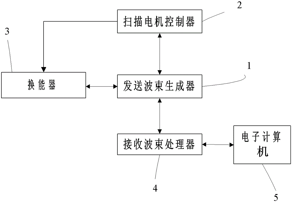
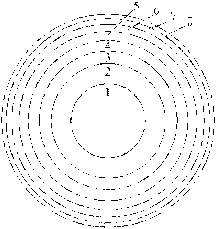
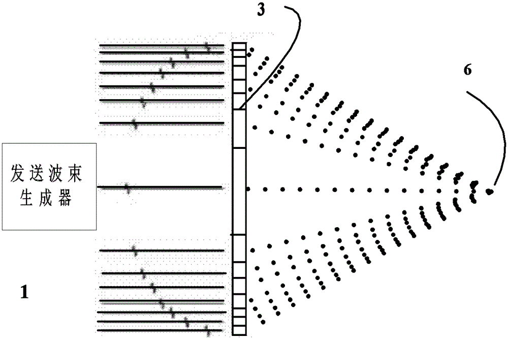
[0027] combine Figure 1 to Figure 9 The principle of the ultrasonic imaging system of the present invention is explained. Such as figure 1 The ultrasonic imaging system of the present invention shown has five main parts: a transducer 3, a transmit beamformer 1 connected thereto, a scanning motor controller connected to the transducer 3 and transmit beamformer 1, and a transmit beamformer The receiving beam processor 4 connected with the device 1 and the electronic computer 5 connected with the receiving beam processor 4. Among them, the transducer 3 is a high-frequency ultrasonic (ultrasonic signal frequency is 15MHZ-80MHZ) transducer, under the excitation of multiple high-voltage pulse signals (excitation signals) with different delays generated by the transmitting beamformer 1, the transducer 3 Generate ultrasonic waves. Under the control of the scanning motor controller 2, the annular array transducer 3 can perform sectoral scanning, horizontal scanning and fixed scanni...
PUM
 Abstract
Description
Claims
Application Information