Harness Connector

a connector and harness technology, applied in the direction of general fasteners, hook fasteners, safety belts, etc., can solve the problems of difficult to open the unlocked connector and many of the existing connector designs, and achieve the effect of preventing the gate opening

Inactive Publication Date: 2019-03-07
MSA TECH
View PDF20 Cites 3 Cited by
  • Summary
  • Abstract
  • Description
  • Claims
  • Application Information

AI Technical Summary

Benefits of technology

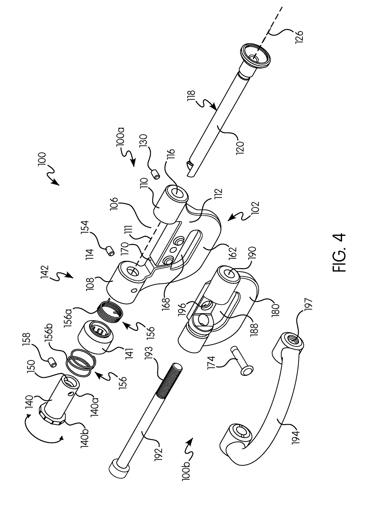
[0007]According to some non-limiting embodiments or aspects, an outer sleeve surrounding at least a portion of the rotatable knob may be provided. The outer sleeve may be axially movable relative to the rotatable knob between a first position and a second position, wherein, in the first position of the outer sleeve, rotational movement of the rotatable knob is prevented, and wherein, in the second position of the outer sleeve, rotational movement of the rotatable knob is permitted. The outer sleeve may be operatively connected with the rotatable knob in the second position of the outer sleeve to permit rotational movement of the rotatable knob with rotational movement of the outer sleeve. The outer sleeve may be axially biased to the first position by a second biasing member.
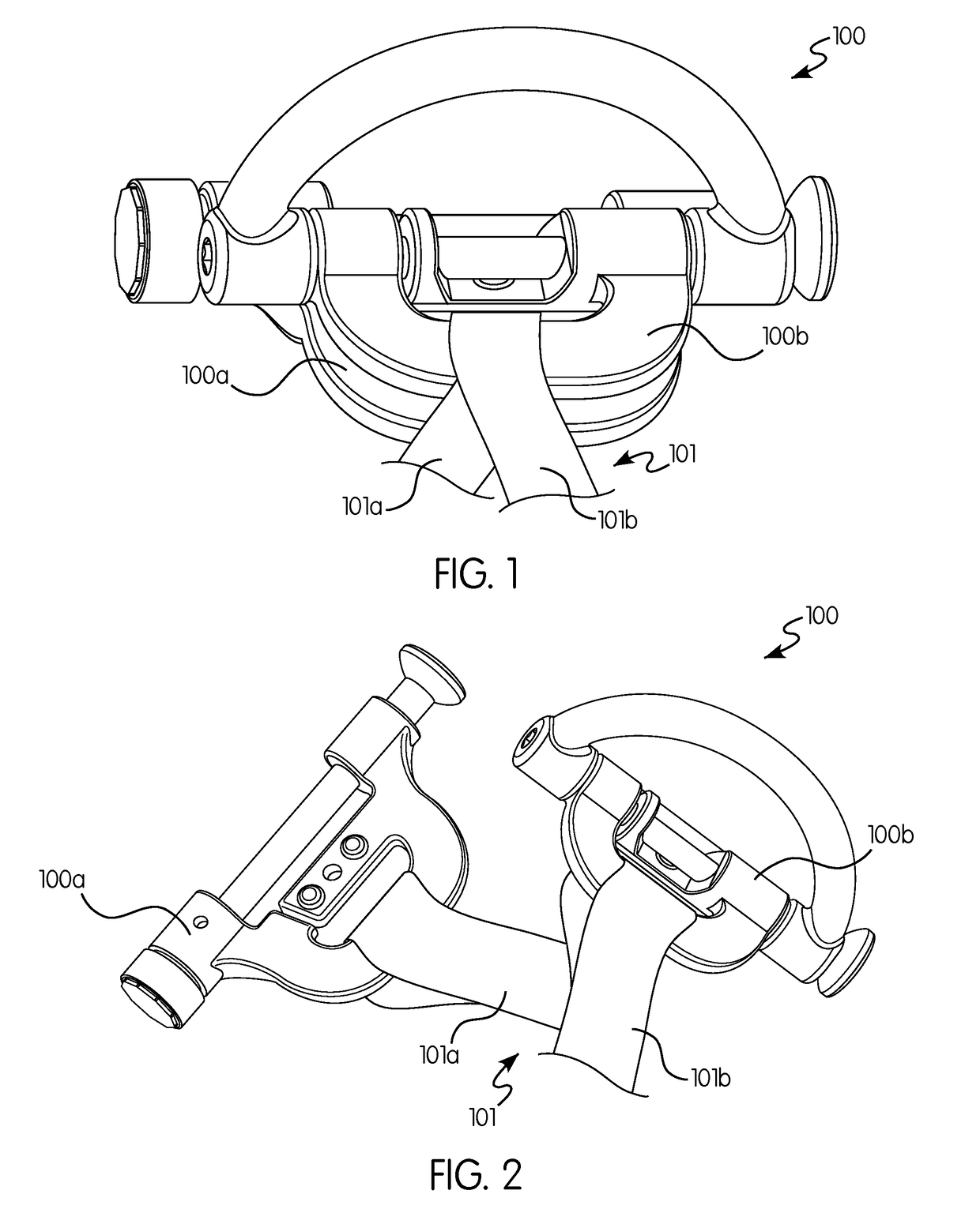
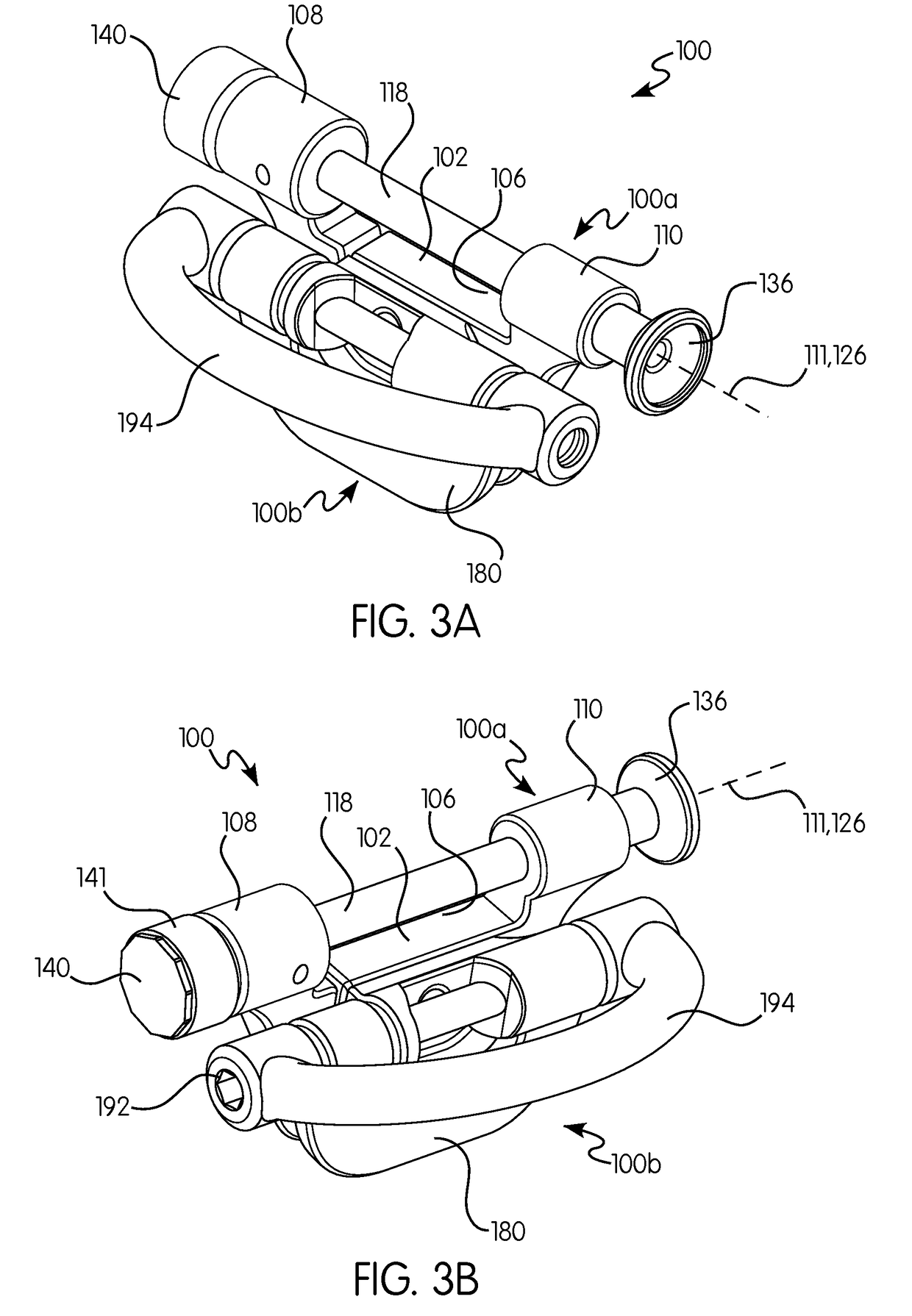
[0008]According to some non-limiting embodiments or aspects, the gate may have an elongated, substantially cylindrical body with a first end and a second end spaced apart along a longitudinal axis of the gate. The locking indent may be positioned at one of the first end and the second end of the gate. The locking indent may have a sloped portion arranged at an angle relative to the longitudinal axis of the gate and a recess arranged substantially perpendicular to the longitudinal axis of the gate. The recess may prevent opening of the gate without rotation of the rotatable knob. The sloped portion may be configured to automatically rotate the rotatable knob to receive the gate when the gate is pushed to a closed position. The cylindrical body of the gate may be movable within a bore extending through the first end of the frame. The gate may have a track extending between the first end and the second end in a direction of the longitudinal axis. The frame may have a detent within the bore of at least one of the first end and the second end of the frame, the detent being received within the track of the gate to delimit longitudinal and rotational movement of the gate relative to the frame. The frame may have an attachment portion with an opening for receiving at least an element of a fall arrest system.

Problems solved by technology

Many of the existing connector designs are difficult to use when operating the two-action locking mechanism then to move the connector between the first and second position.
Some connectors require the unlocking to be performed using both hands, thereby making it difficult to open the unlocked connector because the user does not have a free hand.

Method used


Image

  • Harness Connector
  • Harness Connector
  • Harness Connector

Examples


Embodiment Construction

[0060]Spatial or directional terms, such as “left”, “right”, “inner”, “outer”, “above”, “below”, and the like, are not to be considered as limiting as the invention can assume various alternative orientations. For purposes of the description hereinafter, the terms “end”, “upper”, “lower”, “right”, “left”, “vertical”, “horizontal”, “top”, “bottom”, “lateral”, “longitudinal”, and derivatives thereof shall relate to the invention as it is oriented in the drawing figures.

[0061]As used in the specification and the claims, the singular form of “a”, “an”, and “the” includes plural referents unless the context clearly dictates otherwise.

[0062]All numbers used in the specification and claims are to be understood as being modified in all instances by the term “about”. “About” means a range of plus or minus ten percent of the stated value.

[0063]Unless otherwise indicated, all ranges or ratios disclosed herein are to be understood to encompass any and all subranges or subratios subsumed therein...


PUM


Abstract

A connector includes a frame having a first end, a second end, and a pass-through opening extending between the first end and the second end along a longitudinal axis of the frame. The connector further has a gate positioned between the first end and the second end of the frame and movable between a closed position to close the pass-through opening and an open position to open the pass-through opening. A locking mechanism selectively locks the gate in the closed position. The locking mechanism has a rotatable knob connected to at least one of the first end and the second end of the frame and rotatable in a direction about the longitudinal axis, and a locking indent on the gate configured for receiving at least a portion of the rotatable knob when the gate is in the closed position. The rotatable knob is rotationally biased by a biasing mechanism.

Description

BACKGROUND OF THE INVENTIONField of the Invention[0001]The present disclosure pertains broadly to the field of mechanical connectors. More specifically, the present disclosure relates to mechanical connectors suitable for use in fall-arresting or fall prevention applications.Background of the Invention[0002]In various applications, safety harnesses are used in work environments where there may be a risk of falling from an elevated position. In some applications, a user wearing a safety harness may be connected to a lanyard that is then attached to an anchor point. The lanyard is attached to the harness with a connector which is configured for removably connecting the safety harness with the lanyard.[0003]A wide variety of connectors exists for various applications. In some examples, the connector is movable between a first position, where the connector securely connects the safety harness to the lanyard, and a second position, where the connector allows the safety harness to be disc...

Claims


Application Information

Patent Timeline
Patent Type & Authority Applications(United States)
IPC IPC(8): A44B13/00A62B35/00
CPCA44B13/00A62B35/0037A44D2211/02A44B11/28
Inventor HETRICH, MITCHELL H.PITT, ROBERT
Owner MSA TECH
Why Eureka
Try Eureka