Pneumatic stapler

a stapler and pneumatic technology, applied in the field of pneumatic staplers, can solve the problems of reducing the probability of forming damaged staples, and achieve the effect of high convenience in us

Inactive Publication Date: 2019-03-07
PATEK PNEUMATICS
View PDF0 Cites 0 Cited by
  • Summary
  • Abstract
  • Description
  • Claims
  • Application Information

AI Technical Summary

Benefits of technology

[0005]A primary object of the present invention is to provide a pneumatic stapler that requires only one pressure source to move a staple-driving element and a wire-bending element to a staple-driving position and a wire-bending position, resp

Problems solved by technology

With these arrangements, the wire-bending element won't be too quickly moved and thereby indirectly reduces the p

Method used


Image

  • Pneumatic stapler
  • Pneumatic stapler
  • Pneumatic stapler

Examples


Embodiment Construction

[0040]The present invention will now be described with some preferred embodiments thereof and by referring to the accompanying drawings. For the purpose of easy to understand, elements that are the same in the preferred embodiments are denoted by the same reference numerals.

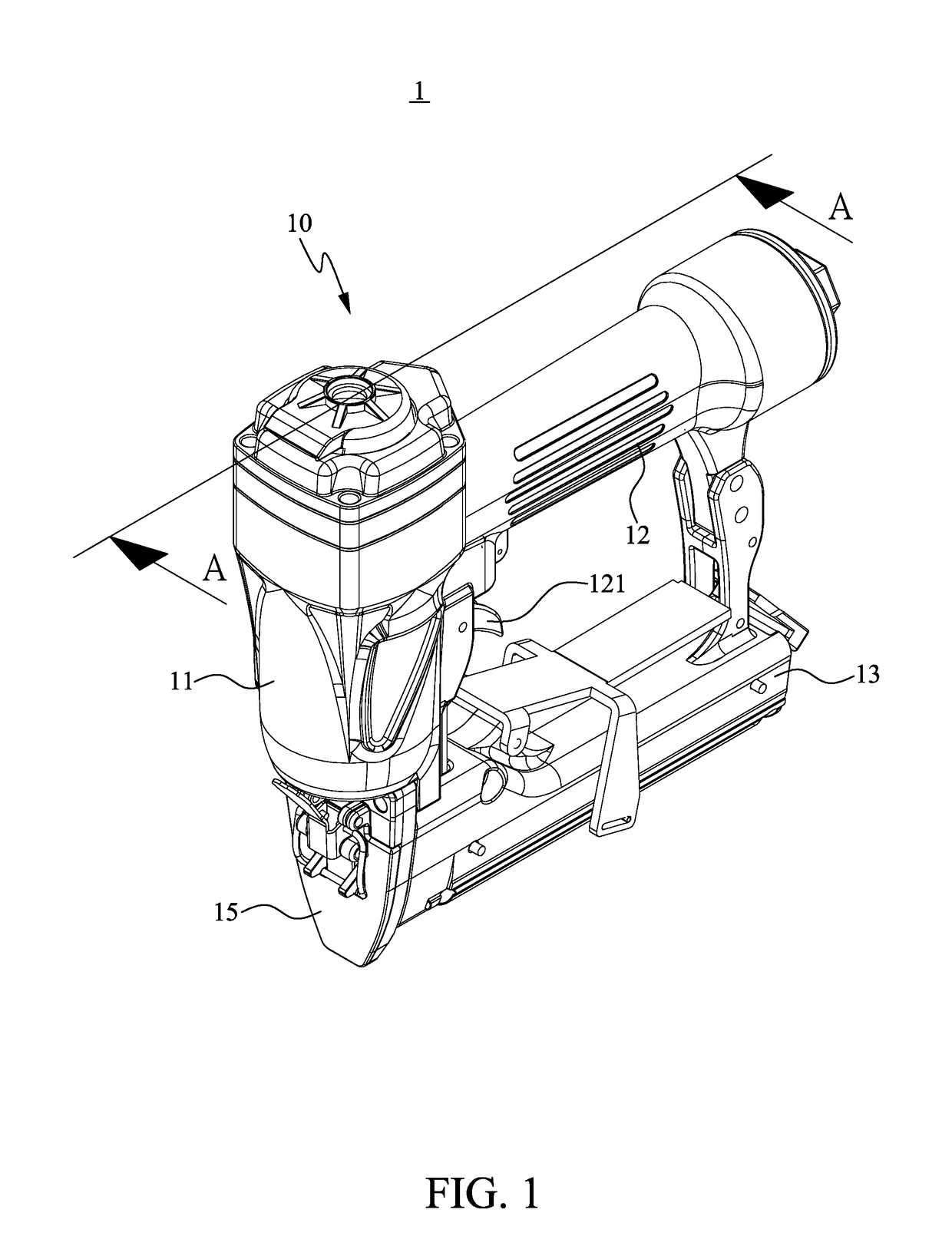
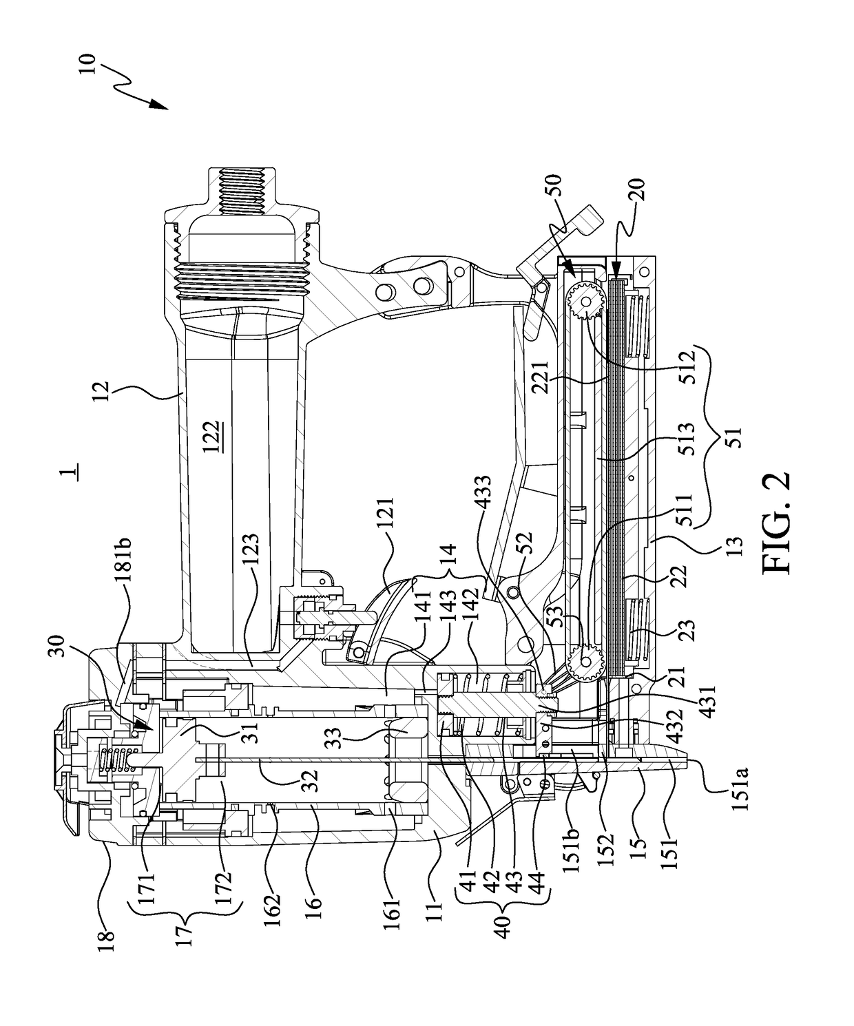
[0041]Please refer to FIGS. 1 and 2. A pneumatic stapler 1 according to a first preferred embodiment of the present invention mainly includes a main body 10, a staple-forming wire storage mechanism 20, a staple-driving mechanism 30, and a wire-bending mechanism 40. The main body 10 includes a staple-driving portion 11 located at a front side of the main body 10, a handle portion 12 sidewardly extended from an end of the staple-driving portion 11 and located at a rear side of the main body 10, and an assemblage portion 13 sidewardly extended from another end of the staple-driving portion 11 opposite to the handle portion 12 and also located at the rear side of the main body 10. The staple-driving portion 11 intern...


PUM


Abstract

A pneumatic stapler has a main body internally loaded with straight staple-forming wires and including a staple-driving and a wire-bending control chamber. A staple-driving element carrier is movably mounted in the staple-driving control chamber and divides the latter into a first and a second staple-driving gas flowing space. When the staple-driving element carrier moves in the second staple-driving gas flowing space to push one staple out of the main body into a workpiece, the initially isolated first staple-driving control chamber is now communicable with the wire-bending control chamber, allowing part of the gas supplied to the pneumatic stapler to flow into the wire-bending control chamber and move a wire-bending element mounted therein to bend one staple-forming wire into a staple. Therefore, the pneumatic stapler requires only one pressure source to complete both staple-driving and wire-bending operations and can have more staple-forming wires loaded therein to provide high convenience in use.

Description

FIELD OF THE INVENTION[0001]The present invention relates to a pneumatic stapler capable of bending straight staple-forming wires into U-shaped staplers while performing a staple-driving operation; and more particularly, to a pneumatic stapler that requires only one pressure source to perform both a staple-driving operation and a wire-bending operation.BACKGROUND OF THE INVENTION[0002]In general woodworking, an interior decorator often uses nails to fixedly connect two or more pieces of wood workpieces to one another. However, there are usually many points between the wood workpieces that require fixed connection, and the interior decorator has to consume a lot of time and effort to manually drive the nails into the workpieces with a hammer at the risk of carelessly injuring his fingers by the hammer. To overcome the above disadvantage, a pneumatic stapler designed for woodworking has been introduced into the market. In the conventional pneumatic stapler, there is a magazine loaded ...

Claims


Application Information

Patent Timeline
IPC IPC(8): B25C5/13B25C5/02
CPCB25C5/13B25C5/0285
Inventor CHEN, HSIEN CHENGWANG, YAO HONG
Owner PATEK PNEUMATICS
Why Eureka
Try Eureka