Mechanical broadhead

a broadhead and mechanical technology, applied in the direction of arrows, etc., can solve the problems of unintended and undesirable blade opening, complicated and sometimes difficult use, and failure of devices, so as to facilitate quick and easy assembly and repair of the broadhead, and minimize friction on blade deployment. , the effect of simplifying the movement of the blad

Active Publication Date: 2019-03-14
GRACE ENG
View PDF2 Cites 0 Cited by
  • Summary
  • Abstract
  • Description
  • Claims
  • Application Information

AI Technical Summary

Benefits of technology

[0008]In one embodiment, the broadhead includes a ferrule having an exterior and defining a ferrule slot, and a blade movably positioned in the ferrule slot, and a retraction element that secures the blade in the retracted mode. The blade can include a first ball and socket member located adjacent the exterior of the ferrule. The retaining element can include a second ball and socket member also located adjacent the exterior of the ferrule. The second ball and socket member engages the first ball and socket member to hold the blade in the retracted mode. The ball and socket members provide an efficient and secure way to lock and release the blades.
[0015]The broadhead of the embodiments herein provides an efficient mechanism by which to securely hold blades of the broadhead in a retracted mode. When utilized, the retainer element can withstand the elements and generally is of a durable, long lasting and optionally reusable construction. Further, the two-part ferrule can provide an efficient way to secure and guide movable blades, yet provide easy access for repair and replacement of the same.

Problems solved by technology

Many of these devices, however, are prone to rotting or cracking, which can lead to failure of the device, and possibly the unintended and undesirable opening of the blades in-flight.
While the clips can retain blades in a retained state, they can be complicated and sometimes difficult to use.

Method used


Image

  • Mechanical broadhead
  • Mechanical broadhead
  • Mechanical broadhead

Examples


Embodiment Construction

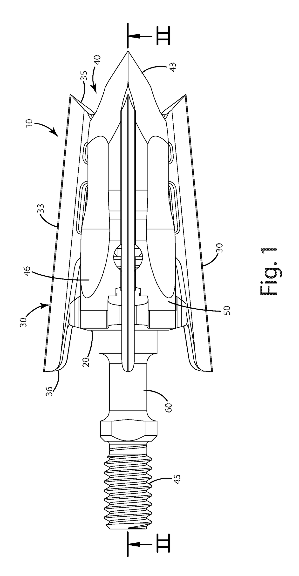
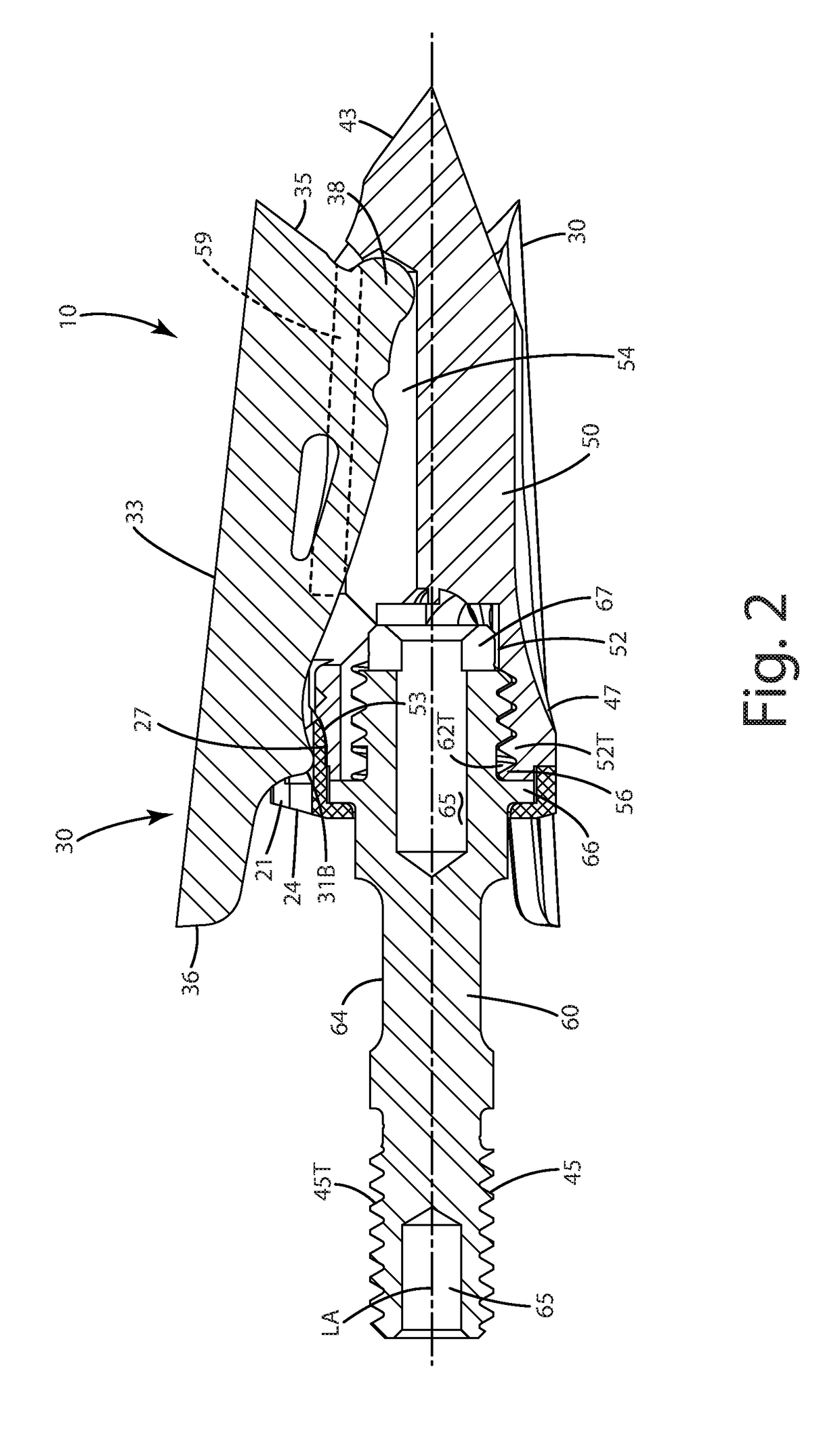
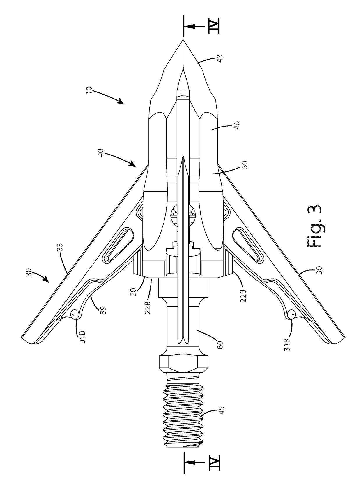
[0028]A current embodiment of the broadhead is shown in FIGS. 1-9 and generally designated 10. The broadhead can include a retainer element 20 and one or more blades 30 joined with a ferrule 40. For purposes of disclosure, the broadhead is described in connection with use on an archery arrow, however, the broadhead is well suited for use with any projectile.

[0029]The broadhead of the current embodiment can be a rearward deploying, sliding blade type broadhead. This type of broadhead transitions from a retracted mode as shown in FIGS. 1-2 to a retracted mode shown in FIGS. 3-4. In the retracted mode, the broadhead is of a smaller cross section so that it performs well in flight. In the expanded mode, the blades 30 are rearwardly deployed to increase the cutting area of the broadhead. The constructions herein also are suitable for use with other rearward deploying broadheads, such as those disclosed in U.S. Pat. No. 6,935,976 to Grace, and U.S. Pat. No. 8,449,416 to Grace, both of whi...


PUM


Abstract

A mechanical broadhead, which has blades movable from a retracted mode to a deployed mode, is provided with ball and socket members that hold the blades in the retracted mode, and selectively release the blades to the deployed mode. The ball and socket members, which can be on the blades and / or on a retainer element, can be snapped together to provide an audible snap confirming locking of the blades in the retracted mode. The mechanical broadhead can include first and second ferrule portions removably joined with one another. The second ferrule portion can acquire a blocking mode to block a removal opening of a ferrule slot defined in the first ferrule portion so that blade cannot be removed from respective ferrule slots. The second ferrule portion can achieve a removal mode so that the blades can be removed from the slots.

Description

BACKGROUND OF THE INVENTION[0001]The present invention relates generally to a mechanical broadhead, and more particularly, to a mechanical broadhead including movable blades, such as rearward deploying / sliding blades or pivoting blades.[0002]A mechanical broadhead, sometimes referred to as an expanding blade broadhead, includes blades joined with a ferrule so that the blades can move from a retracted in-flight position to a deployed position upon engagement with a target. Mechanical broadheads generally have the flight characteristics of a field point, yet the penetration and cutting characteristics of a fixed blade broadhead.[0003]One type of mechanical broadhead is a pivoting blade broadhead. This broadhead includes blades located in a slot defined by a ferrule so that the cutting edges of the blades face inward in the retracted, in-flight position. The blades are pivotally joined with the ferrule at their rear so they can rotate from the retracted, in-flight position to a deploye...

Claims


Application Information

Patent Timeline
Patent Type & Authority Applications(United States)
IPC IPC(8): F42B6/08
CPCF42B6/08
Inventor GRACE, NATHANIEL E.
Owner GRACE ENG
Why Eureka
Try Eureka