
Micromechanical component, method for manufacturing a micromechanical component, and method for exciting a movement of an adjustable part about a rotational axis

a micromechanical component and rotating axis technology, applied in the field of micromechanical components, can solve the problems of hardly/unattainable, energetically inefficient, etc., and achieve the effect of facilitating the minimization of the micromechanical componen

Active Publication Date: 2019-04-25
ROBERT BOSCH GMBH
View PDF17 Cites 8 Cited by
  • Summary
  • Abstract
  • Description
  • Claims
  • Application Information

AI Technical Summary

Benefits of technology

The present invention provides a micromechanical component that can move or oscillate in multiple directions using gyroscopic effects. The use of four piezoelectric bending actuators requires low excitation voltages and contributes to energy efficiency. Unlike conventional drives, the present invention is more energy-efficient. This also means that the traditional need for connecting permanent magnets and coils to the adjustable part is dispensed with. The invention allows for a static or quasi-static deflection of the adjustable part about a rotational axis using purely resonant excitations. The micromechanical component is space-saving and easy to suspend and adjust. This invention provides a promising option for creating compact and efficient micromechanical components.

Problems solved by technology

In this way, the adjustable part may be rotated about the rotational axis, even when a “direct excitation” of a rotation of the adjustable part about the rotational axis is energetically inefficient or hardly / not achievable.

Method used


Image

  • Micromechanical component, method for manufacturing a micromechanical component, and method for exciting a movement of an adjustable part about a rotational axis
  • Micromechanical component, method for manufacturing a micromechanical component, and method for exciting a movement of an adjustable part about a rotational axis
  • Micromechanical component, method for manufacturing a micromechanical component, and method for exciting a movement of an adjustable part about a rotational axis

Examples


Embodiment Construction

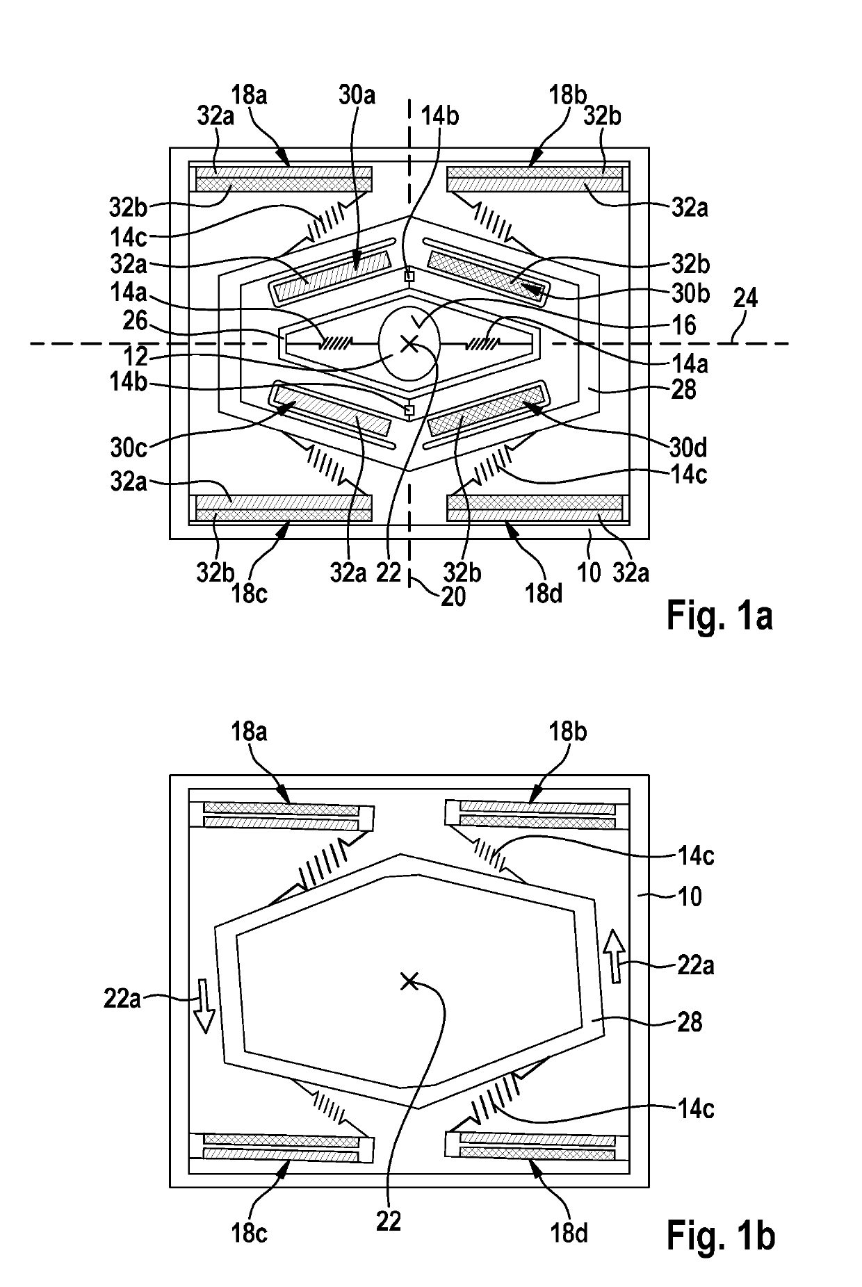
[0020]FIGS. 1a and 1b show schematic illustrations for explaining an operating principle of a first specific embodiment of the micromechanical component.

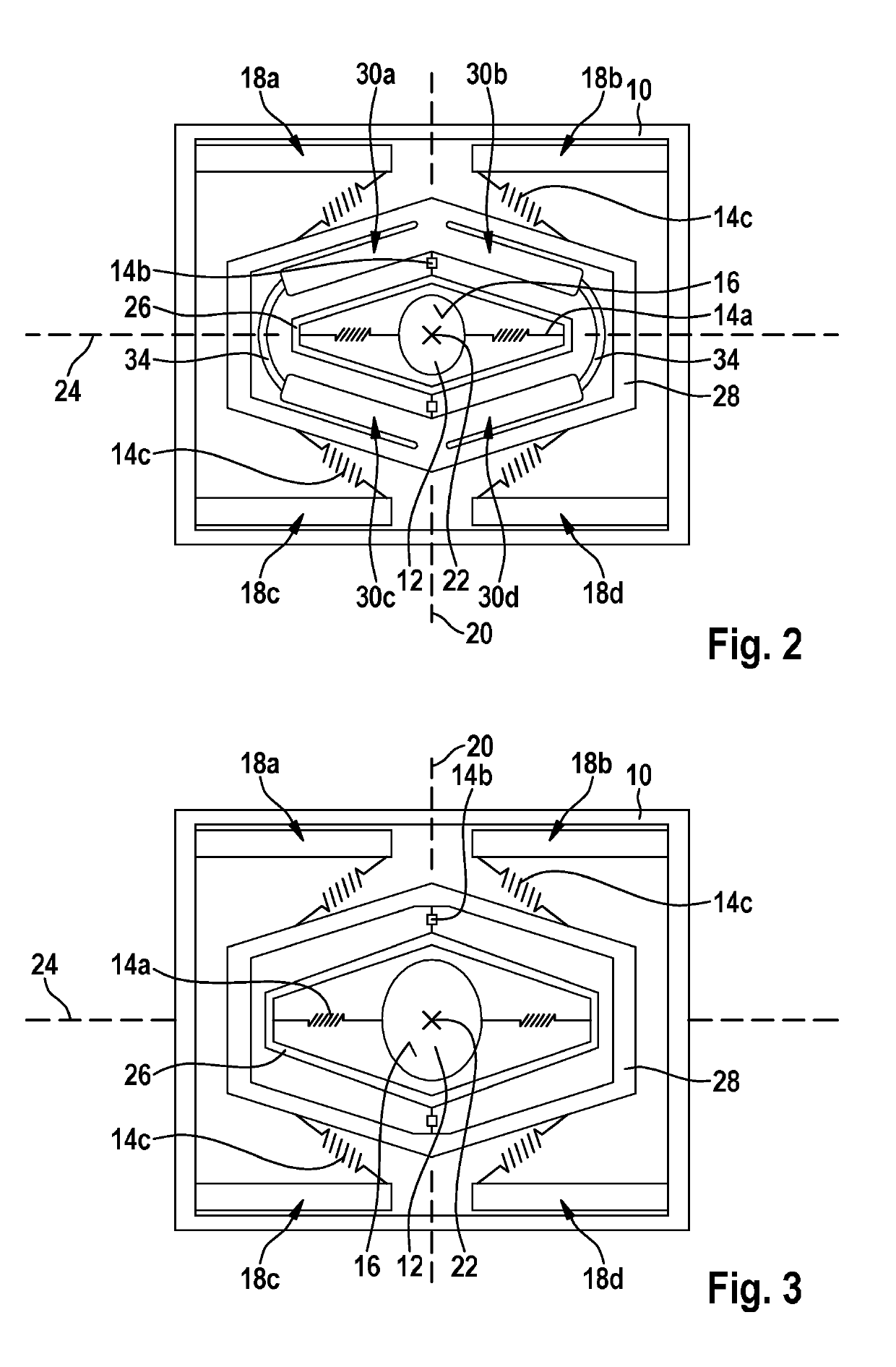
[0021]The micromechanical component schematically illustrated in FIG. 1a includes a mounting 10 and an adjustable part 12, adjustable part 12 being connected, at least via springs 14a through 14c, to mounting 10. As an example, adjustable part 12 is a mirror plate 12 having a reflective surface 16. However, it is pointed out that a configuration of adjustable part 12 is not limited to the example depicted in FIG. 1a.

[0022]The micromechanical component also includes an (only partially depicted) actuator device 18a through 18d and 30a through 30d that is configured in such a way that a first oscillating motion of adjustable part 12 is excitable, in relation to mounting 10, about a first rotational axis 20 with the aid of actuator device 18a through 18d and 30a through 30d. At the same time (as the first oscillating motion of adjustab...


PUM


Abstract

A micromechanical component, including an adjustable part that is connected, at least via springs, to the mounting, and an actuator device with which a first oscillating motion of the adjustable part is excitable about a first rotational axis and at the same time a second oscillating motion of the adjustable part is excitable about a second rotational axis. The actuator device includes four piezoelectric bending actuators, and the adjustable part is settable into the first oscillating motion and / or into the second oscillating motion by deformation of the four piezoelectric bending actuators, and each of the four piezoelectric bending actuators at its first end is anchored to the mounting, and the adjustable part is suspended, at least via the springs, on the four piezoelectric bending actuators.

Description

RELATED APPLICATION INFORMATION[0001]The present application claims priority to and the benefit of German patent application no. 10 2017 217 653.9, which was filed in Germany on Oct. 5, 2017, the disclosure which is incorporated herein by reference.FIELD OF THE INVENTION[0002]The present invention relates to a micromechanical component. Moreover, the present invention relates to a method for manufacturing a micromechanical component. Furthermore, the present invention relates to a method for exciting a movement of an adjustable part about a rotational axis.BACKGROUND INFORMATION[0003]Patent document DE 10 2012 219 591 A1 discusses a micromechanical component that includes an adjustable part that is connected to a mounting via springs. In addition, on each spring the micromechanical component includes at least one attached bending actuator whose shape is changeable, by provision of at least one electrical signal, in such a way that the adjustable part is adjustable into a movement ab...

Claims


Application Information

Patent Timeline
Patent Type & Authority Applications(United States)
IPC IPC(8): G02B26/08F16M11/18G02B26/10H01L41/09
CPCG02B26/0858F16M11/18G02B26/10H01L41/094H02N2/108F16M11/125H10N30/2042
Inventor KAUPMANN, PHILIP
Owner ROBERT BOSCH GMBH
Learn More