Cheek and tongue retractor

a retractor and tongue technology, applied in the field of dental appliances, can solve the problems that the conventional retractor can also be difficult to use, and achieve the effect of improving the use effect of the retractor and reducing the difficulty of us

Active Publication Date: 2019-05-02
KING SAUD UNIVERSITY
View PDF1 Cites 0 Cited by
  • Summary
  • Abstract
  • Description
  • Claims
  • Application Information

AI Technical Summary

Benefits of technology

[0004]The retractor is a generally U-shaped device for protecting the cheek and tongue from instruments used during dental and prosthodontic procedures. The retractor has a planar base defined by two spaced arms, a pair of upr

Problems solved by technology

As such, conventional retractor

Method used


Image

  • Cheek and tongue retractor
  • Cheek and tongue retractor
  • Cheek and tongue retractor

Examples


Embodiment Construction

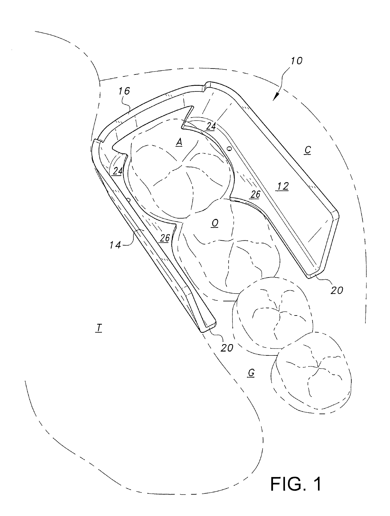
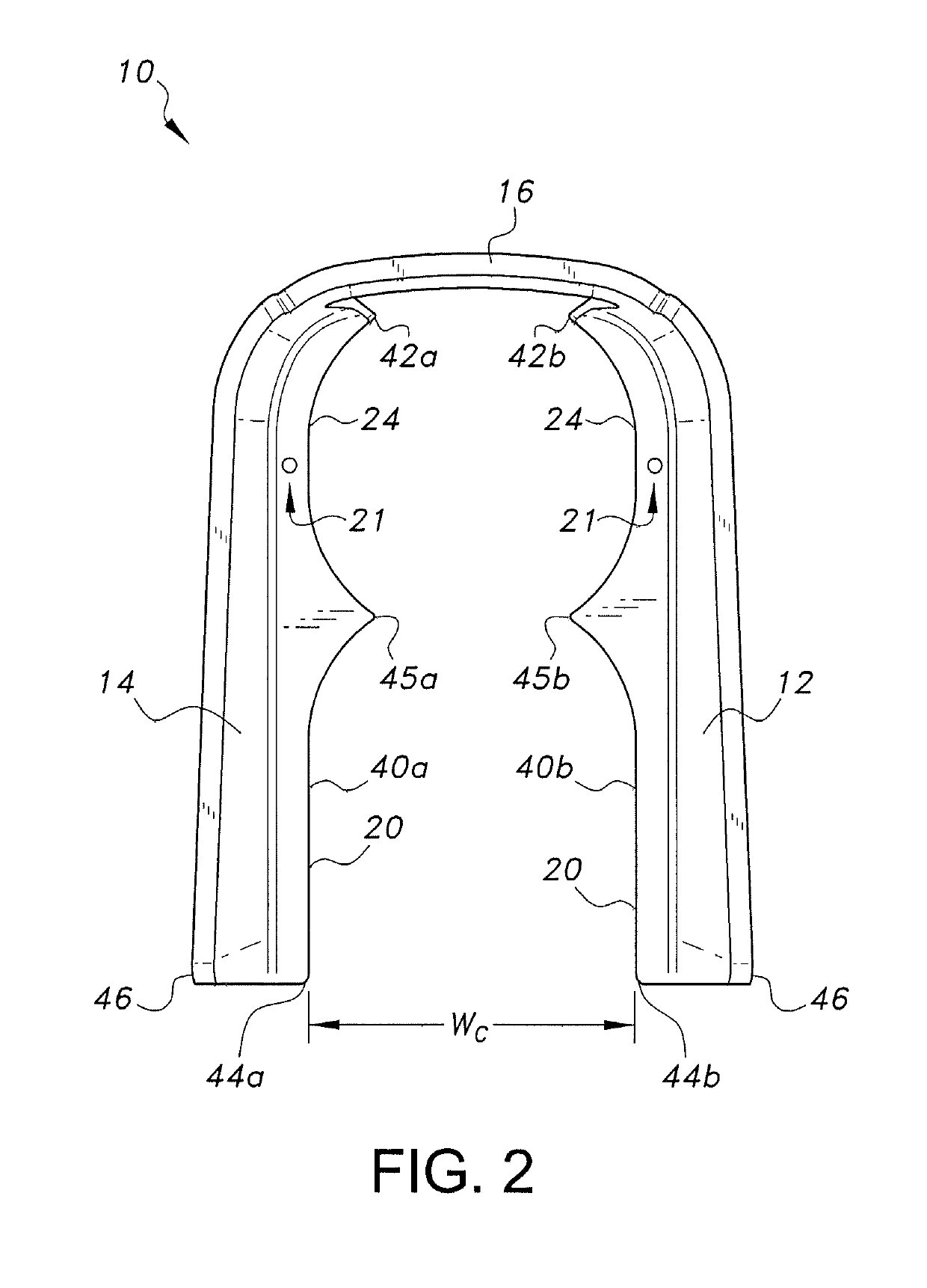
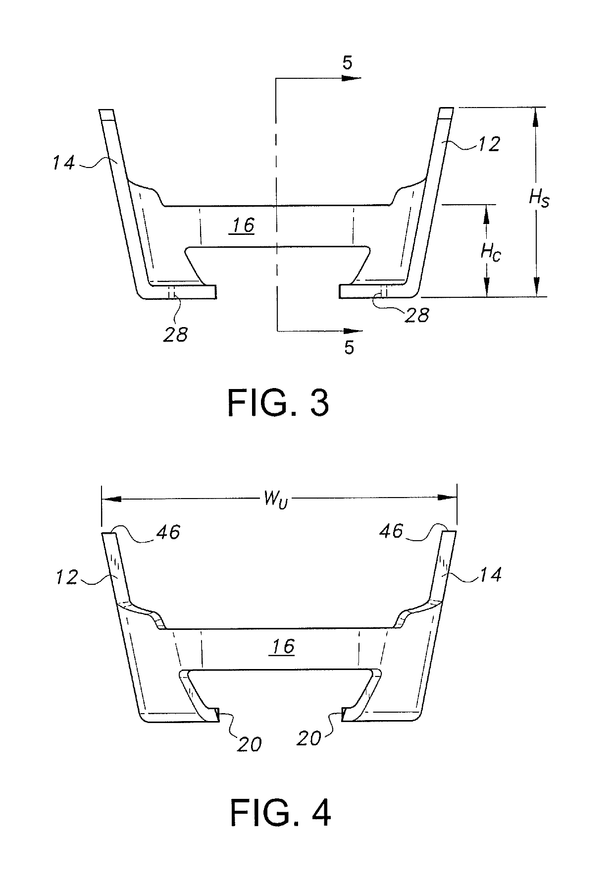
[0013]The cheek and tongue retractor 10 can be used to protect the cheek and tongue from instruments used during dental and prosthodontic procedures. As is shown in FIGS. 1-6, the retractor 10 is a generally U-shaped device having a planar base 20, a buccal shield 12, a lingual shield 14, and a posterior connector 16 connecting the buccal shield 12 and the lingual shield 14. The base 20 is defined by a pair of spaced arms 40a, 40b. The buccal shield 12 and the lingual shield 14 extend generally upright from the arms 40a and 40b.

[0014]The base 20 is contoured to grip the tooth adjacent to the tooth to be treated, and thereby, secure the retractor 10 within the patient's mouth. Once secured to the adjacent tooth, the buccal shield 12 and the lingual shield 14 of the retractor 10 protect the check and tongue of the patient from instruments used during a procedure. It should be understood that the retractor 10 is self-retentive. In other words, an additional force is not required to ho...


PUM


Abstract

The retractor is a generally U-shaped device for protecting the cheek and tongue from instruments used during dental and prosthodontic procedures. The retractor has a planar base defined by two spaced arms, a pair of upright shields extending from the arms, and a posterior connector connecting the shields. The base is contoured to grip the tooth adjacent to the tooth to be treated, and thereby, secure the retractor within the patient's mouth.

Description

BACKGROUND1. Field[0001]The disclosure of the present patent application relates to dental appliances, and particularly to a cheek and tongue retractor for restorative and prosthodontic treatment.2. Description of the Related Art[0002]During restorative dentistry and prosthodontic procedures, clinicians are often required to utilize carbide and / or diamond burs for drilling, finishing, and / or grinding at high speeds. To protect the tongue and cheek of the patient during these procedures, clinicians typically use cheek and tongue retractors. Many conventional retractors, however, include hinged joints, mirrors, and / or handles, which can block or minimize a work area in the mouth. Further, the clinician must grasp a retractor handle to maintain the retractor in a desired position during the procedure. As such, conventional retractors can also be difficult to use.[0003]Thus, a cheek and tongue retractor for restorative and prosthodontic treatment solving the aforementioned problems is d...

Claims


Application Information

Patent Timeline
IPC IPC(8): A61C5/90A61B13/00
CPCA61C5/90A61B13/00A61B1/24A61C5/80
Inventor ALZAIN, SAHAR ASAAD
Owner KING SAUD UNIVERSITY
Why Eureka
Try Eureka