Supercharge Your Innovation With Domain-Expert AI Agents!

Sensor logic control of gun camera

Active Publication Date: 2019-05-16
STEWART DAVID A
View PDF2 Cites 2 Cited by
  • Summary
  • Abstract
  • Description
  • Claims
  • Application Information

AI Technical Summary

Benefits of technology

This patent is about a device that helps hunters control when a camera wakes up and records video and data from their shots. It uses sensors to monitor the gun and the environment, and sends signals to the camera to determine when it should wake up and start recording. This allows hunters to analyze the video and data from their shots, improving their accuracy.

Problems solved by technology

Capturing the video of events important to a shooter is a challenge.

Method used

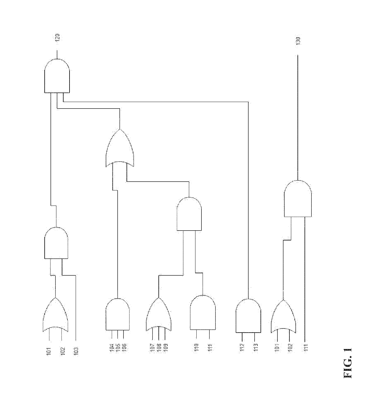
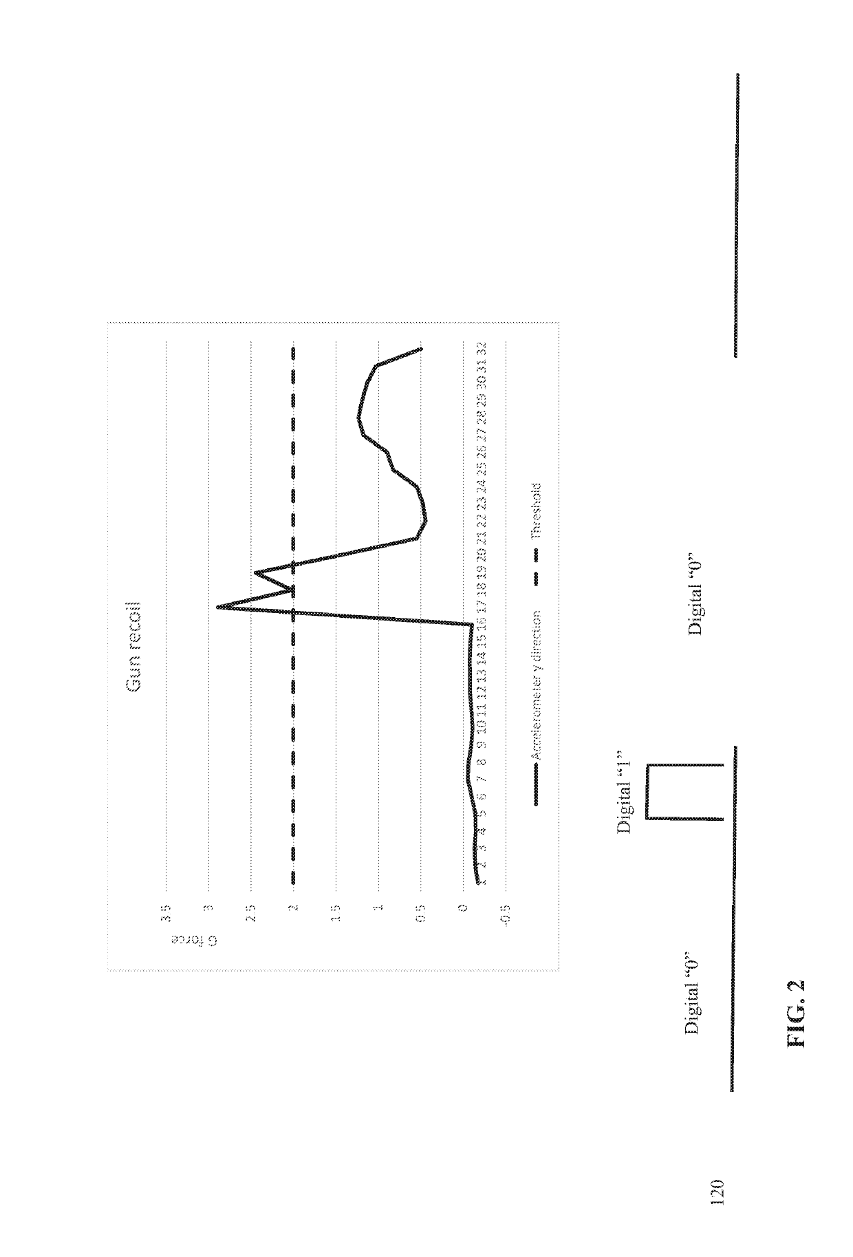
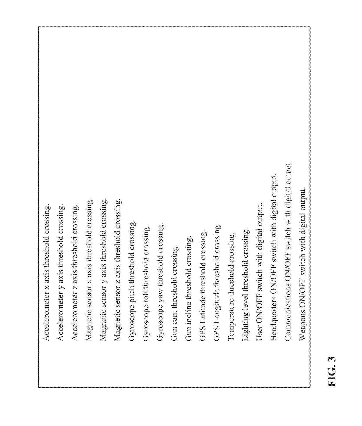

Image

  • Sensor logic control of gun camera
  • Sensor logic control of gun camera
  • Sensor logic control of gun camera

Examples


Embodiment Construction

[0023]The present invention is generally directed to the process for the capture of video, slow motion, still images, and target shooting data. More particularly, the present invention relates to controlling video and data capture to give the shooter the visual representation of the target, or the shooter, or both.

[0024]Some advantages of the methods of the present invention include, in certain embodiments, the ability to allow the system to go into sleep mode during times when shots are not being taken. The ability to only record the useful video and data in the times just before during and after the shot.

[0025]As employed above and throughout the disclosure, the following terms, unless otherwise indicated, shall be understood to have the following meanings.

[0026]The examples provided in the definitions present in this application are non-inclusive unless otherwise stated. They include but are not limited to the recited examples.

[0027]As used herein, the term “shooting device” incl...


PUM


Abstract

The present invention relates to the process where a gun video camera is controlled by logic functions using inputs from sensors monitoring the gun and environmental characteristics. More particularly, a control signal is generated which determines the wake-up time of a camera in sleep mode and the recording time of video and data capture of the camera.

Description

FIELD OF THE INVENTION[0001]This invention generally relates to cameras mounted on firearms and more specifically to processes for controlling the timing of video capture of images of a target, and / or the shooter.BACKGROUND OF THE INVENTION[0002]Video mounted camera on fire arms have been around for years. Capturing the video of events important to a shooter is a challenge. Shooters do not want to edit video or waste storage on recording video that does not capture data relevant to their shots.SUMMARY OF THE INVENTION[0003]The invention will aid the shooter by letting them control the parameters which cause the video camera to wake-up and record video and data from their shots.[0004]This invention has specific application in the hunting, target shooting, military, and law enforcement fields. However, it can be utilized in any field where it is helpful to control a video camera on a shooting device. The primary example used in the figures and description will be the case in which a p...

Claims


Application Information

Patent Timeline
IPC IPC(8): G03B29/00G06F1/3206H04N5/232H04N5/76F41J5/10
CPCG03B29/00G06F1/3206H04N5/232411H04N5/76F41J5/10F41A33/00F41G3/2605H04N5/772G06F1/1686G06F1/1694G06F1/325G06F1/3287Y02D10/00H04N23/60H04N23/651
Inventor STEWART, DAVID A.
Owner STEWART DAVID A
Features
  • R&D
  • Intellectual Property
  • Life Sciences
  • Materials
  • Tech Scout
  • Unparalleled Data Quality
  • Higher Quality Content
  • 60% Fewer Hallucinations
Learn More