Heat transfer device

Inactive Publication Date: 2019-05-30
DGSHAPE CORP
View PDF5 Cites 2 Cited by
  • Summary
  • Abstract
  • Description
  • Claims
  • Application Information

AI Technical Summary

Benefits of technology

[0008]In the above-described heat transfer device, in the state where the holder is not holding

Problems solved by technology

However, the presser is not always attached to the foil transfer tool such as a laser pen or the like because, for exampl

Method used


Image

  • Heat transfer device
  • Heat transfer device
  • Heat transfer device

Examples


Embodiment Construction

[0026]Hereinafter, heat transfer devices according to preferred embodiments the present invention will be described with reference to the drawings. The preferred embodiments described herein are not intended to specifically limit the present invention. Components and portions that have the same functions will bear the same reference signs, and overlapping descriptions will be omitted or simplified.

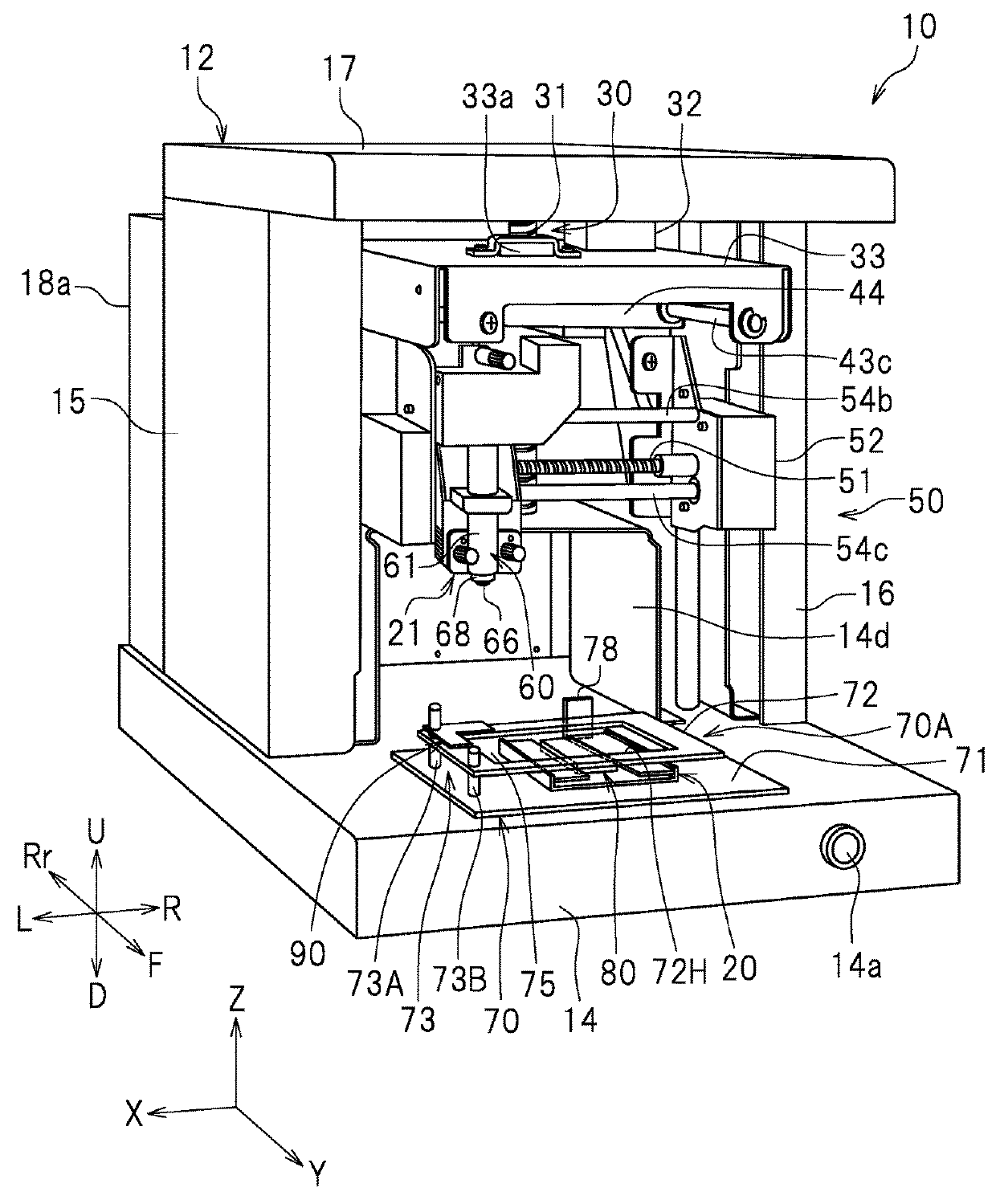
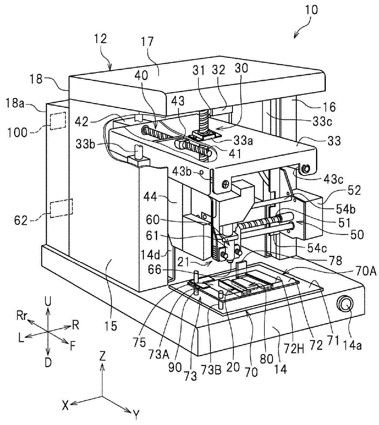
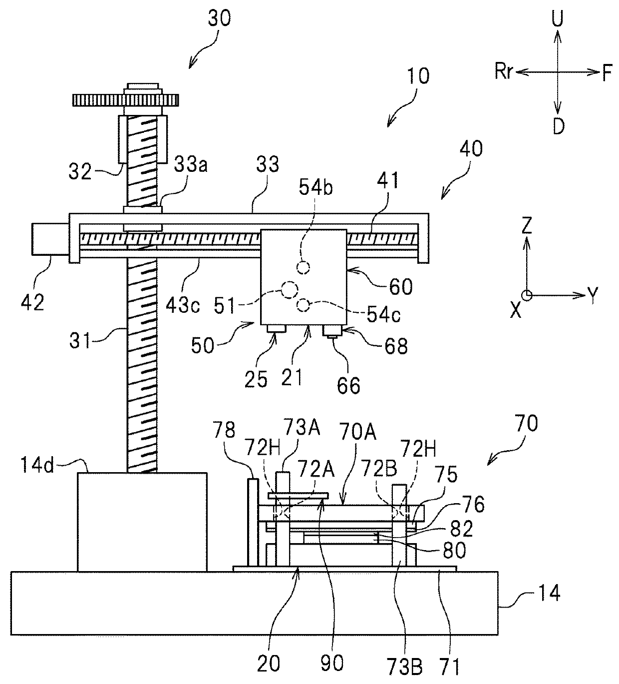
[0027]FIG. 1 is a perspective view of a heat transfer device 10. FIG. 2 is a partially cut perspective view schematically showing the heat transfer device 10. FIG. 3 is a left side view schematically showing head moving mechanisms and a holding table 70. In the following description, the terms “left”, “right”, “up” and “down” respectively refer to left, right, up and down as seen from an operator (user) looking at a power button 14a on a front surface of the heat transfer device 10. A direction approaching the heat transfer device 10 away from the operator is referred to as “rearward”, and...


PUM


Abstract

In a heat transfer device, a holder holds a presser such that a portion of the presser protrudes downward. At a position where a holding portion of the holder that is holding the presser is above an inspection surface, a first height at which a foil transfer tool collides against the inspection surface is measured. At a position where the holding portion of the holder is outward of the inspection surface and a portion of a bottom end of the holder other than the holding portion is above the inspection surface, a second height at which the foil transfer tool collides against the inspection surface is measured. If a difference between the first height and the second height is smaller than a predetermined difference, it is determined that the holder is not holding the presser.

Description

CROSS REFERENCE TO RELATED APPLICATIONS[0001]This application claims the benefit of priority to Japanese Patent Application No. 2017-229115 filed on Nov. 29, 2017. The entire contents of this application are hereby incorporated herein by reference.BACKGROUND OF THE INVENTION1. Field of the Invention[0002]The present invention relates to a heat transfer device, and more specifically to a heat transfer device that performs foil transfer on a transfer target by use of a heat transfer foil.2. Description of the Related Art[0003]Conventionally, a decoration process is performed by a heat transfer method by use of a heat transfer foil (also referred to as a “heat transfer sheet”) for the purpose of providing a better design or the like. The heat transfer foil roughly includes a substrate, a decoration layer and an adhesive layer stacked in this order. Foil transfer is performed (namely, the heat transfer foil is transferred onto the transfer target) as follows. The heat transfer foil is s...

Claims


Application Information

Patent Timeline
IPC IPC(8): B32B41/00B32B37/00
CPCB32B41/00B32B37/025B41F16/0046B44C1/1729B41F16/00B65C1/00
Inventor KANNO, YUKIEOGAWA, TAMAKIUEDA, JUN
Owner DGSHAPE CORP
Why Eureka
Try Eureka