
Display module

Pending Publication Date: 2022-09-29
WUHAN CHINA STAR OPTOELECTRONICS SEMICON DISPLAY TECH CO LTD
View PDF3 Cites 0 Cited by
  • Summary
  • Abstract
  • Description
  • Claims
  • Application Information

AI Technical Summary

Benefits of technology

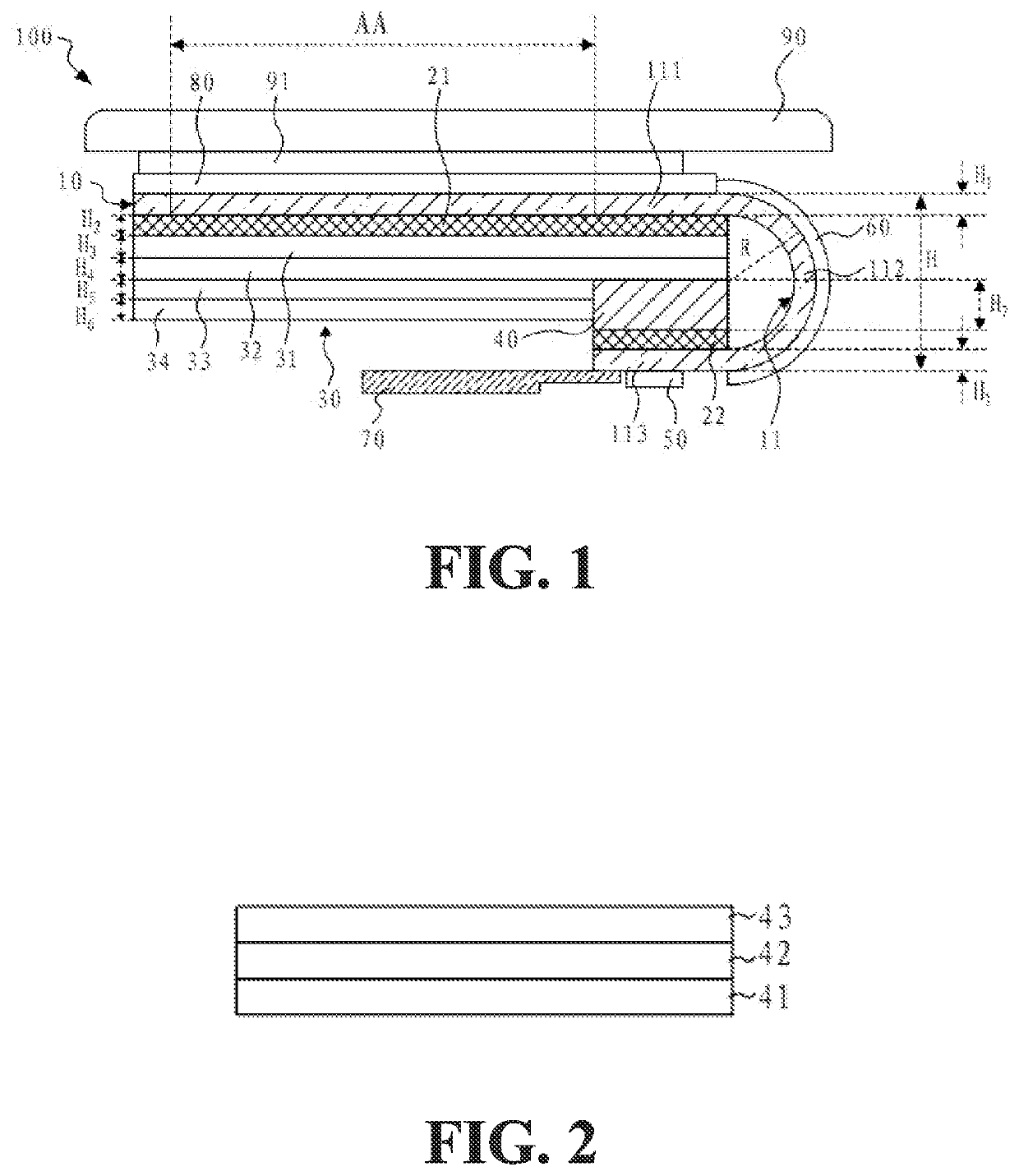
The invention relates to a screen protector for electronic devices, specifically a display module for displays in screens in electronic devices. The invention improves the structure of the display module by placing a reinforcement plate in a receiving slot in the screen protector, which reduces the overall height of the bending region and meets the requirements for a display module with a radius of curvature of 0.2 millimeters or less. Additionally, the invention enhances the reliability of the bending bonding end by improving adhesion of the reinforcement plate during bending. Overall, the invention improves the structural integrity and reliability of the screen protector for electronic devices.

Problems solved by technology

However, a thin thickness of the reinforcement plate affects its adhesion, which influences reliability of bending of the bonding region.

Method used


Image

  • Display module
  • Display module
  • Display module

Examples


Embodiment Construction

[0033]The present invention provides a display module. To make the objective, the technical solution, and the effect of the present invention clearer and more explicit, the present invention will be further described in detail below with reference to the accompanying drawings. It should be understood that the specific embodiments described here are only used to explain the present invention instead of being used to limit the present invention.

[0034]The present invention aims at the technical issue that in a conventional display module, to achieve a design of a narrow bezel and an ultra-thin module, it is required to design the thickness of the reinforcement plate thinner, which results in poor adhesion and affects reliability of bending of the bonding region. The present embodiment can solve the defects.

[0035]With reference to FIG. 1, an embodiment of the present invention provides a display module 100 comprising a display panel 10, a first backplate 21, a super clean foam (SCF) ass...


PUM


Abstract

A display module includes a display panel, a first backplate, a super clear foam (SCF) assembly and a reinforcement plate. The first backplate is disposed on a side of a display panel opposite to a light emission surface. The SCF assembly and the reinforcement plate are disposed on a side of the first backplate opposite to the display panel. A receiving slot is defined in a side of the SCF assembly opposite to display panel. At least one part of the reinforcement plate is received in the receiving slot, and a driver chip is located on a side of the reinforcement plate opposite to the display panel.

Description

FIELD OF INVENTION[0001]The present invention relates to a field of display technologies, especially relates to a display module.BACKGROUND OF INVENTION[0002]As display parts of electronic devices, display modules have been extensively applied to various electronic products. Designs of narrow bezels and ultra-thin modules are also increasingly favored by terminal manufacturers and consumers. End consumers' demands to a size of a bezel of a display module and a thickness of a display module become stricter. Designing a structure of a module with a narrow bezel and a ultra-thin thickness is an urgent issue to be solved.[0003]Achievement of a narrow bezel solution mainly relies on bending of a bonding region such that a driver chip is bent to a rear of a display module. The rear of the display panel of the display module is attached with a structure of a super clean foam (SCF) and a reinforcement plate. The SCF structure functions as a cushion and the reinforcement plate performs a bon...

Claims


Application Information

Patent Timeline
IPC IPC(8): H01L51/52H05K5/00H05K7/20
CPCH01L51/529H05K5/0017H05K7/20954G09F9/30G09F9/301G09F9/33H10K59/8794H10K77/111H10K50/87
Inventor XIA, HAO
Owner WUHAN CHINA STAR OPTOELECTRONICS SEMICON DISPLAY TECH CO LTD
Learn More