Object detection and image cropping using a multi-detector approach

a multi-detector, object detection technology, applied in image enhancement, instruments, computing models, etc., can solve the problems of difficult or impossible object detection, difficulty in object detection, and frustration of the process of determining background and foreground characteristics

Active Publication Date: 2019-05-30
KOFAX
View PDF0 Cites 35 Cited by
  • Summary
  • Abstract
  • Description
  • Claims
  • Application Information

AI Technical Summary

Problems solved by technology

However, images captured using flat-bed scanners, MFPs, etc. tend to exhibit oversaturation, which can make detecting the edges of objects (or equivalently, transition from the image background to the object or image foreground) difficult or impossible.
The relatively small size causes difficulty in object detection, since there is relatively less information available for use in determining characteristics of the foreground and distinguishing the same from the background.
Unknown / unexpected orientation and position can similarly frustrate the process of determining background and foreground characteristics, for instance because it can be difficult to sample characteristics from a predetermined region with confidence the characteristics truly correspond only to the background or foreground / object.
However, as noted above images captured using cameras and the like are characterized by inherent distortion and / or warping.
Moreover, in general the capture conditions surrounding use of a camera are more variable and less capable of control than corresponding conditions when capturing image data using a flat-bed scanner, MFP, or the like.
Lighting conditions, camera motion and / or relative position to the object, and presence of complex backgrounds are particularly challenging aspects of capturing image data using a camera and which frustrate or even defeat the ability to perform desired processing of the captured image data, e.g. object detection and accurate cropping.

Method used


Image

  • Object detection and image cropping using a multi-detector approach
  • Object detection and image cropping using a multi-detector approach
  • Object detection and image cropping using a multi-detector approach

Examples


Embodiment Construction

[0029]The following description is made for the purpose of illustrating the general principles of the present invention and is not meant to limit the inventive concepts claimed herein. Further, particular features described herein can be used in combination with other described features in each of the various possible combinations and permutations.

[0030]Unless otherwise specifically defined herein, all terms are to be given their broadest possible interpretation including meanings implied from the specification as well as meanings understood by those skilled in the art and / or as defined in dictionaries, treatises, etc.

[0031]It must also be noted that, as used in the specification and the appended claims, the singular forms “a,”“an” and “the” include plural referents unless otherwise specified.

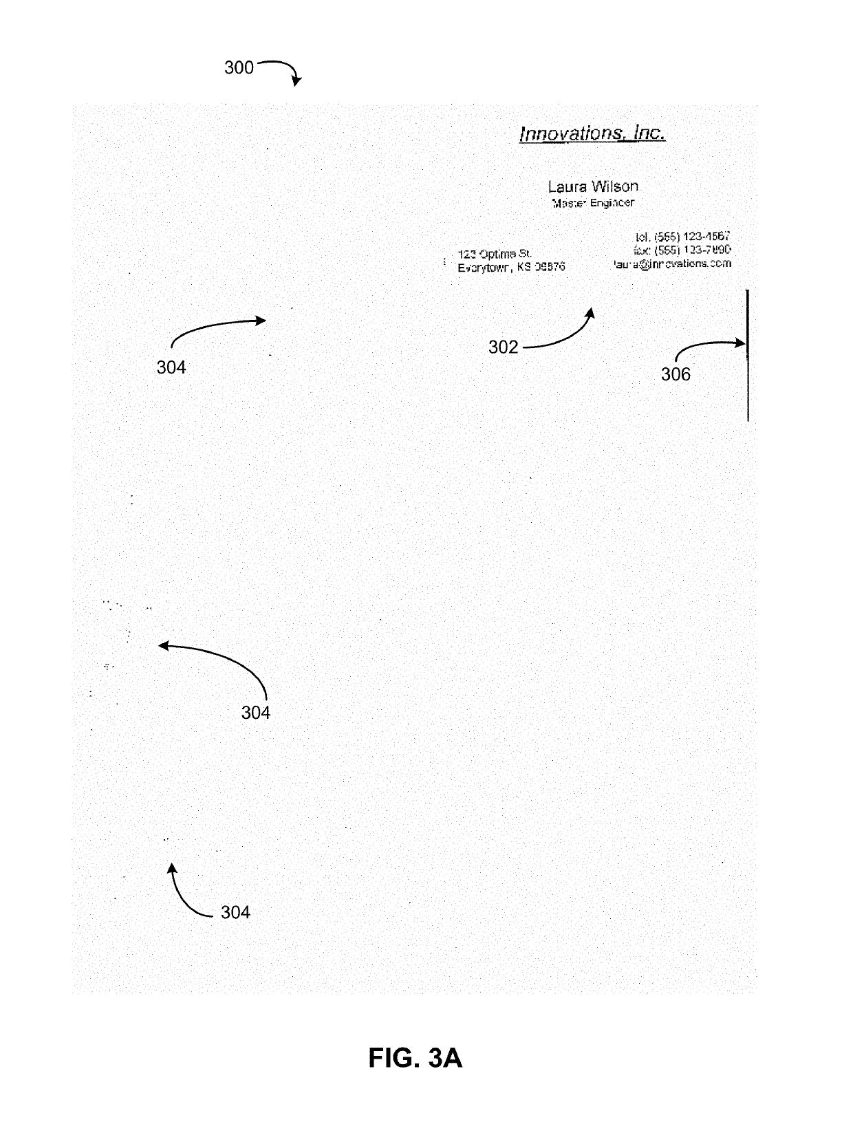
[0032]As referred-to herein, it should be understood that the term “connected component” refers to any structure within an image, preferably a bitonal image that is formed from a contiguous set...


PUM


Abstract

Computerized techniques for real-time object detection from video data include: defining an analysis profile comprising an initial number of analysis cycles dedicated to each of a plurality of detectors, each detector being independently configured to detect objects according to a unique set of analysis parameters; receiving a plurality of frames of digital video data, the digital video data depicting an object; analyzing the plurality of frames using the plurality of detectors and in accordance with the analysis profile, wherein analyzing the plurality of frames produces an analysis result for each of the plurality of detectors; determining a confidence score for each of the analysis results; and updating the analysis profile by adjusting the number of analysis cycles dedicated to at least one of the plurality of detectors based on the confidence scores. Corresponding systems and computer program products are also disclosed.

Description

RELATED APPLICATIONS[0001]This application is related to U.S. Pat. No. 9,779,296, granted Oct. 3, 2017 and entitled “Content-Based Detection And Three Dimensional Geometric Reconstruction Of Objects In Image And Video Data.”; U.S. Pat. No. 9,760,788, granted Sep. 12, 2017 and entitled “Mobile Document Detection And Orientation Based On Reference Object Characteristics”; U.S. Pat. No. 9,355,312, granted May 31, 2016 and entitled “Systems And Methods For Classifying Objects In Digital Images Captured Using Mobile Devices”; U.S. Pat. No. 9,208,536, granted Dec. 8, 2015 and entitled “Systems And Methods For Three Dimensional Geometric Reconstruction Of Captured Image Data;” and U.S. Pat. No. 8,855,375, granted Oct. 7, 2014 and entitled “Systems and Methods for Mobile Image Capture and Processing”; each of which is herein incorporated by reference in its entirety.FIELD OF INVENTION[0002]The present invention relates to image capture and image processing. In particular, the present invent...

Claims


Application Information

Patent Timeline
Patent Type & Authority Applications(United States)
IPC IPC(8): G06K9/62G06K9/00G06T7/90G06T7/13G06T7/70G06K9/46G06T7/194G06V10/44G06V10/762G06V30/10G06V30/162
CPCG06K9/6227G06K9/00711G06K9/6262G06T7/90G06T7/13G06T7/70G06K9/4604G06T7/194G06T2207/10016G06T2207/10024G06K9/38G06T2207/30176G06T7/12G06T2207/20081G06N20/00G06V30/413G06V30/2253G06V10/44G06V30/10G06V30/147G06V30/162G06V30/18105G06V10/762G06V10/809G06V30/19173G06V30/19147G06N7/01G06F18/23G06F18/254G06V20/40G06F18/285G06F18/217G06V10/28G06T7/11G06N7/00G06T7/0002
Inventor MA, JIYONGTHOMPSON, STEPHEN M.AMTRUP, JAN W.
Owner KOFAX
Why Eureka
Try Eureka