Air Deflector Assembly For An Automotive Vehicle

Active Publication Date: 2019-06-06
GM GLOBAL TECH OPERATIONS LLC
View PDF4 Cites 0 Cited by
  • Summary
  • Abstract
  • Description
  • Claims
  • Application Information

AI Technical Summary

Benefits of technology

This patent provides a system that can increase the amount of downforce a vehicle has when it needs to without affecting its overall design or causing more drag.

Problems solved by technology

As an automotive vehicle travels, it disturbs the air through which it passes.

Method used


Image

  • Air Deflector Assembly For An Automotive Vehicle
  • Air Deflector Assembly For An Automotive Vehicle
  • Air Deflector Assembly For An Automotive Vehicle

Examples


second embodiment

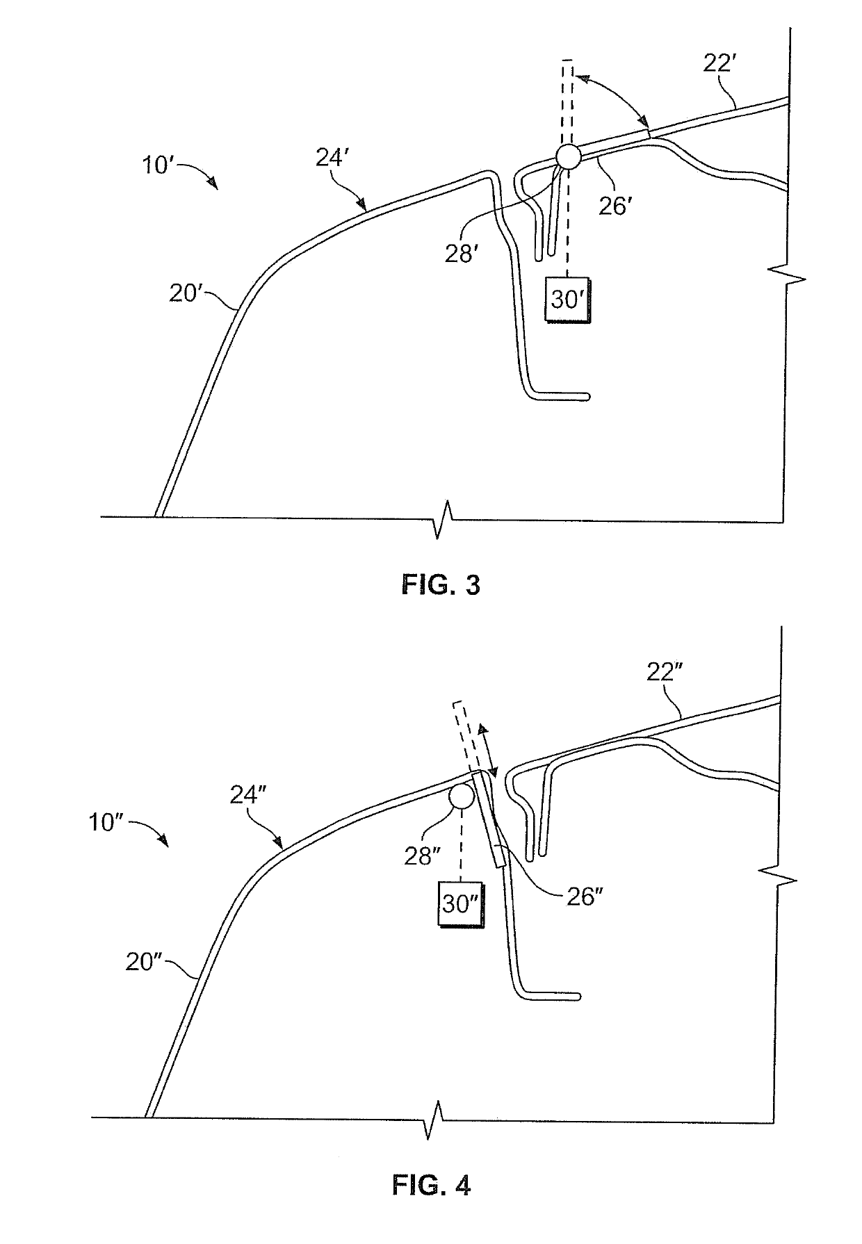
[0036]Referring now to FIG. 3, a second embodiment according to the present disclosure is illustrated. In this embodiment, a vehicle 10′ is provided with a front fascia 20′ and a closure panel 22′, which cooperatively define an upper surface 24′ in a generally similar manner as discussed above with respect to FIGS. 1 and 2. An air deflector 26′ is provided at the upper surface 24′. In this embodiment, the air deflector 26′ has a fore edge pivotably coupled to the closure panel 22′ at a location aft of the front fascia 22′. An actuator 28′ is provided under the control of a controller 30′. The actuator 28′ is configured to, in response to a command from the controller 30′, pivot the air deflector 26′ relative to the closure panel 22′ such that an aft edge of the air deflector 26′ projects away from the closure panel 22′.

third embodiment

[0037]Referring now to FIG. 4, a third embodiment according to the present disclosure is illustrated. In this embodiment, a vehicle 10″ is provided with a front fascia 20″ and a closure panel 22″, which cooperatively define an upper surface 24″ in a generally similar manner as discussed above with respect to FIGS. 1 and 2. An air deflector 26″ is provided at the upper surface 24″. In this embodiment, the air deflector 26″ is movably coupled to the front fascia 20″ and configured to translate relative to the front fascia 20″ in a generally vertical direction. In this embodiment, the air deflector 26″ is disposed at a cut line between the front fascia 20″ and the closure panel 22″; however, in other embodiments the air deflector 26″ may be disposed in other locations on the upper surface 24″. An actuator 28″ is provided under the control of a controller 30″. The actuator 28″ is configured to, in response to a command from the controller 30″, actuate the air deflector 26″ to translate ...


PUM


Abstract

An automotive vehicle includes a body with an upper surface defined by a front fascia disposed proximate a fore end, and a closure panel with a fore edge proximate the front fascia. A deflector with a first end and a second end is movably coupled to the upper surface and is movable between a stowed position and a deployed position. In the stowed position the second end projects a first distance from the upper surface and in the deployed position the second end projects a second distance from the upper surface. The second distance is greater than the first distance. A controller is configured to, in response to satisfaction of a first operating condition, control an actuator to move the deflector from the stowed position to the deployed position.

Description

TECHNICAL FIELD[0001]The present disclosure relates to automotive vehicles, and more particularly to aerodynamic features of automotive vehicles.INTRODUCTION[0002]As an automotive vehicle travels, it disturbs the air through which it passes. As the air passes over the vehicle, the air may impart force on the vehicle. Force imparted by air in a direction opposite vehicle motion may be referred to as drag force, while force imparted in a vertical direction may be referred to as lift force if oriented in an upward direction or as downforce if oriented in a downward direction. Vehicle designers therefore design the bodies of vehicles to support desired performance characteristics, accounting for drag, lift, and downforce.SUMMARY[0003]An automotive vehicle according to the present disclosure includes a body with a fore end, an aft end, a longitudinal axis extending from the fore end to the aft end, and a lateral axis extending orthogonal to the longitudinal axis. The body includes a fron...

Claims


Application Information

Patent Timeline
IPC IPC(8): B62D25/08B62D37/02B62D25/10
CPCB62D25/085B62D37/02B62D25/10B62D25/105B62D35/005
Inventor DEL GAIZO, STEVEN A.
Owner GM GLOBAL TECH OPERATIONS LLC
Why Eureka
Try Eureka