
Vacuum cleaner

a vacuum cleaner and vacuum handle technology, applied in vacuum cleaners, suction handles, domestic applications, etc., can solve the problems of increasing complexity and functionality of vacuum cleaners, affecting the use prone to damage, so as to reduce the risk of the pistol grip (or the user's hand) obscuring the effect of the vacuum cleaner, easy to see, and convenient for the user

Active Publication Date: 2019-06-20
DYSON TECH LTD
View PDF0 Cites 10 Cited by
  • Summary
  • Abstract
  • Description
  • Claims
  • Application Information

AI Technical Summary

Benefits of technology

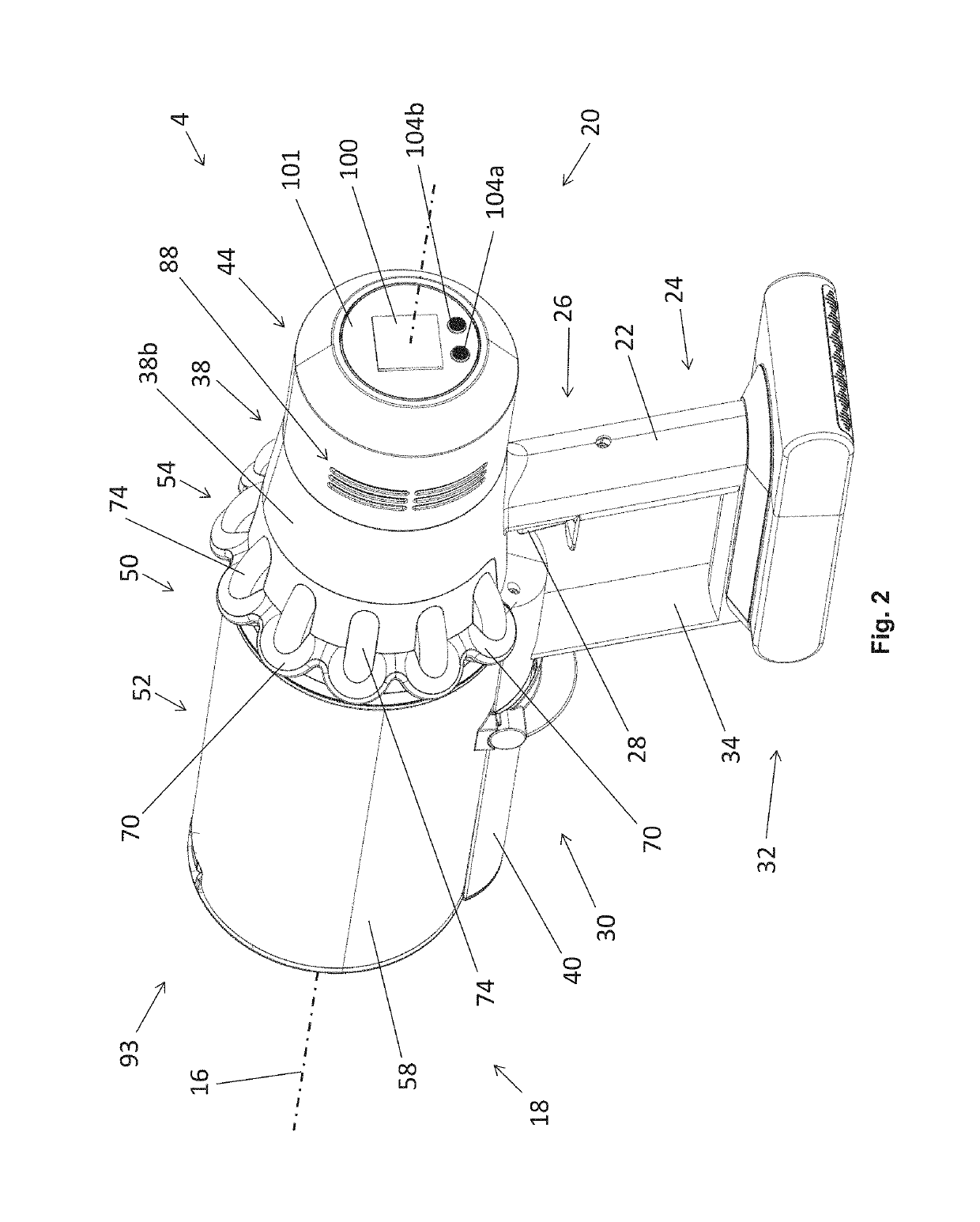
[0064]This may make the electronic visual display easier for the user to see, for instance avoiding the possibility of the pistol grip (or the user's hand) obscuring part of the electronic visual display.
[0065]As an alternative, the electronic visual display may be positioned axially in line with or in front of the pistol grip, in which case it may be displaced from the pistol grip in a radial direction about the longitudinal axis so as to reduce the risk of the pistol grip (or the user's hand) obscuring it.

Problems solved by technology

As vacuum cleaners increase in complexity and functionality, it can be necessary for the vacuum cleaner to convey information to the user such as the suction power level the vacuum cleaner is in or the potential occurrence of a fault.
However, such a display can be relatively delicate and prone to damage, and can add complexity to the vacuum cleaner in that they require electrical wiring to be provided so that electrical information / power can be delivered to them.

Method used


Image

  • Vacuum cleaner
  • Vacuum cleaner
  • Vacuum cleaner

Examples


Embodiment Construction

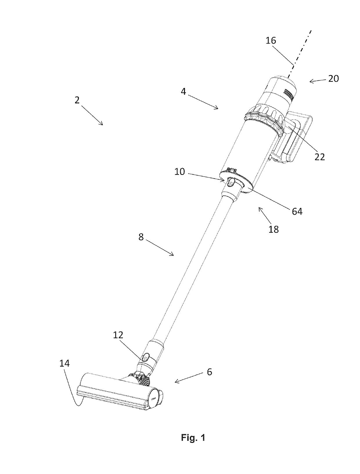
[0091]FIG. 1 shows a stick vacuum cleaner 2 according to an embodiment of the invention. The stick vacuum cleaner comprises a handheld vacuum cleaner 4 which is connected to a floor tool 6 in the form of a cleaner head by an elongate rigid wand 8. In this case the wand is attachable to an air inlet 10 of the handheld vacuum cleaner, and to a rear duct 12 of the cleaner head 6. The wand 8 is generally tubular, the space inside forming a suction path which extends from the cleaner head 6 to the air inlet 10 of the handheld vacuum cleaner 4.

[0092]The cleaner head 6 has a sole plate 14 which is configured to engage a floor surface, and which has a suction opening (not visible) through which dirty air (i.e. air with entrained dirt) from the floor surface can be sucked into the cleaner head 6. A vacuum motor (not visible) which comprises an electric motor and an impeller is housed in the handheld vacuum cleaner 4. In use, the electric motor rotates the impeller about a motor axis (not vis...


PUM


Abstract

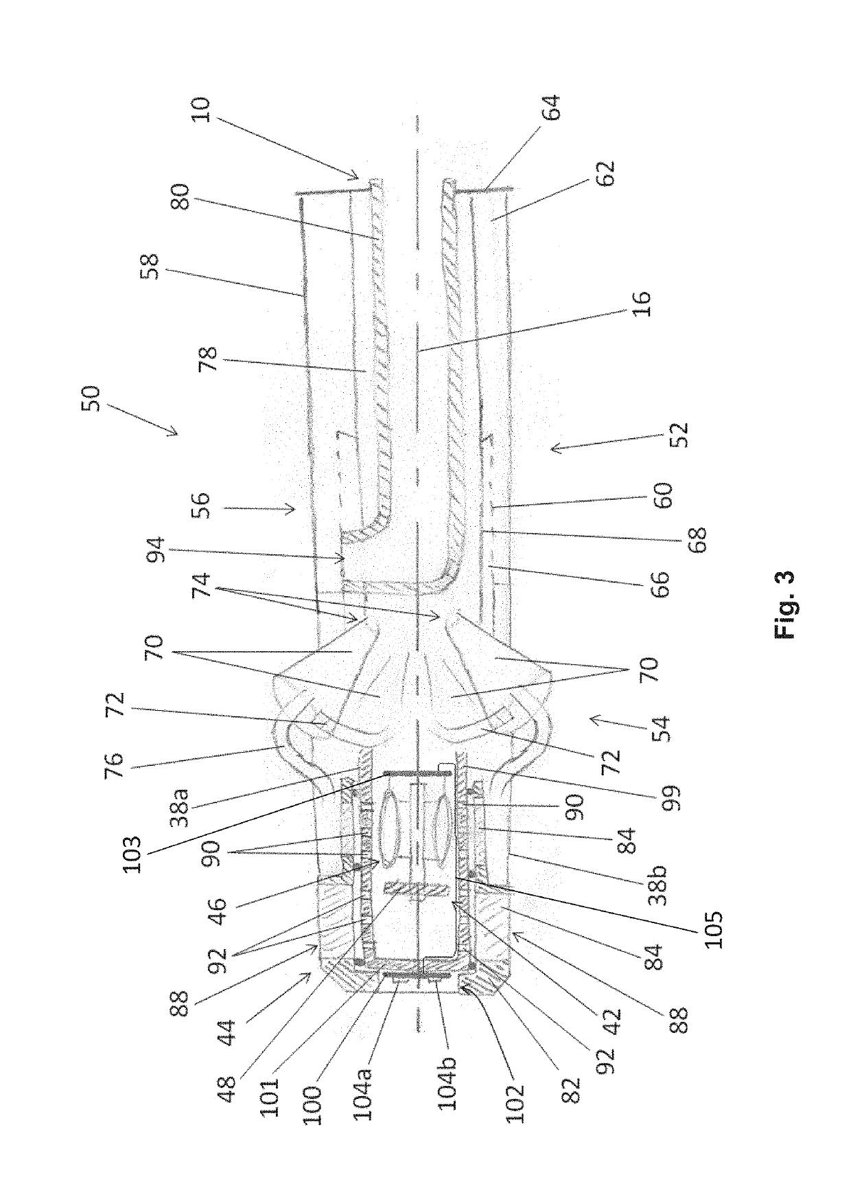
A vacuum cleaner includes a suction nozzle for drawing dirty air into the vacuum cleaner and an exhaust for expelling cleaned air out of the vacuum cleaner; and an air flow passage extending from the suction nozzle to the exhaust through a dirt separator. The vacuum cleaner further includes a vacuum motor arranged to draw a flow of air through the vacuum cleaner from the suction nozzle to the exhaust, the vacuum motor comprising an electric motor and an impeller which rotates about a motor axis. The vacuum cleaner further includes an electronic visual display configured to display information relating to the vacuum cleaner. The vacuum motor is housed inside a motor bucket which is positioned in the flow passage, and the electronic visual display is mounted to the motor bucket and supported thereby.

Description

REFERENCE TO RELATED APPLICATIONS[0001]This application claims priority of United Kingdom Application No. 1721489.1, filed Dec. 20, 2017, and United Kingdom Application No. 1818286.5, filed Nov. 9, 2018, the entire contents of which are incorporated herein by reference.FIELD OF THE INVENTION[0002]The present invention relates to the field of vacuum cleaners.BACKGROUND OF THE INVENTION[0003]As vacuum cleaners increase in complexity and functionality, it can be necessary for the vacuum cleaner to convey information to the user such as the suction power level the vacuum cleaner is in or the potential occurrence of a fault. One way to display such information is to use an electronic visual display. However, such a display can be relatively delicate and prone to damage, and can add complexity to the vacuum cleaner in that they require electrical wiring to be provided so that electrical information / power can be delivered to them.SUMMARY OF THE INVENTION[0004]According to some aspects, a v...

Claims


Application Information

Patent Timeline
Patent Type & Authority Applications(United States)
IPC IPC(8): A47L9/28A47L5/28A47L9/32A47L9/12
CPCA47L9/2857A47L5/28A47L9/32A47L9/127A47L5/24A47L9/322A47L9/248A47L5/12A47L9/00A47L9/28A47L9/22
Inventor KING, KRISTIAN RICHARD THOMASRIDLEY, THOMAS DOUGLASMILLINGTON, DAVID ALANBOYCE, DAVID NICHOLASLEA, ALAN JOHN
Owner DYSON TECH LTD
Learn More