
Security door hinge assembly

Active Publication Date: 2019-06-20
HODGSON SAYERS LTD
View PDF14 Cites 1 Cited by
  • Summary
  • Abstract
  • Description
  • Claims
  • Application Information

AI Technical Summary

Benefits of technology

The invention is a security door hinge assembly that can be completely hidden when the door is closed. It is designed to prevent access to the hinge mechanism from both sides, increasing security. The hinge is able to manipulate a door that is larger than the opening, and when the door is closed, the hinge is ineffective, further increasing security.

Problems solved by technology

Estate security is expensive to implement and maintain across a large regional or national geographic area, often because the dynamics of the threat can be locally influenced.
Threats are dynamic, thus frequently making existing security systems redundant before the capital expenditure has been amortized.
Furthermore, nowadays, any type of information is instantly accessible via Internet based search engines and anybody can make themselves more familiar with suitable attack methods in order to try and gain access into secured premises and sites under risk may be forced to constantly improve and / or replace their security systems.
In order to achieve a higher security rating, it is very common to simply replace the existing design with the same design but using thicker and more “exotic” materials, though, those “high-end” products are usually much more expensive than the replaced “lower-end” product.
It is known that hinges are usually a weak point of a security door system, because the hinge action requires sufficient space to allow for full movement of the door(s).
However, currently available hinge assemblies will still be vulnerable to an attack from a different location and / or different ‘angles’.

Method used


Image

  • Security door hinge assembly
  • Security door hinge assembly
  • Security door hinge assembly

Examples


Embodiment Construction

)

[0058]The exemplary embodiment(s) of this invention will be described in relation to a hinge assembly for security doors and in particular a double-door security door system. However, it should be appreciated that, in general, the concealment characteristics of the hinge assembly of the present invention will work equally well with any other door, flap, gate or any other pivotably arranged closure member.

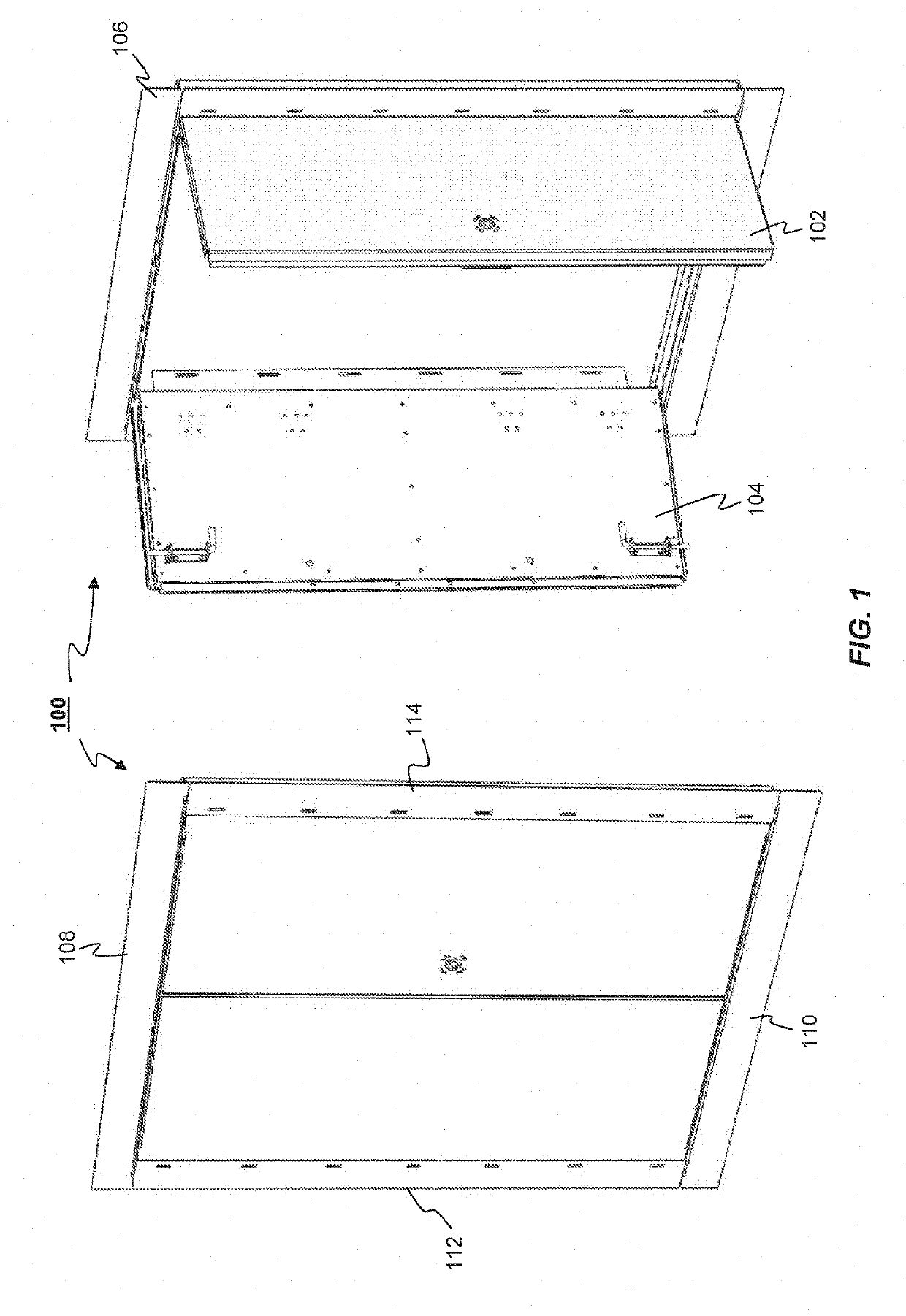
[0059]Referring now to FIG. 1, a security door system 100 comprising the concealed hinge assembly (not shown) is shown in (a) a closed position as seen from the outside and (b) an open position as seen from the outside (i.e. outside the premises). In this particular example embodiment, the security door system 100 is a double-door set having an active door leaf assembly 102 and an inactive door leaf assembly 104, and a frame structure 106 that comprises a head member 108, a sill member 110 and two jamb members 112 and 114. The frame structure 106 may be fitted within a rebate of a ...


PUM


Abstract

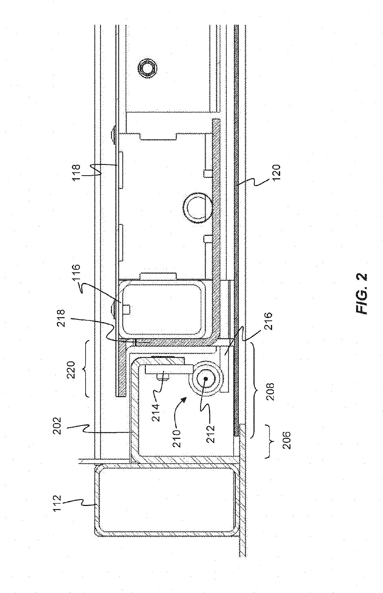
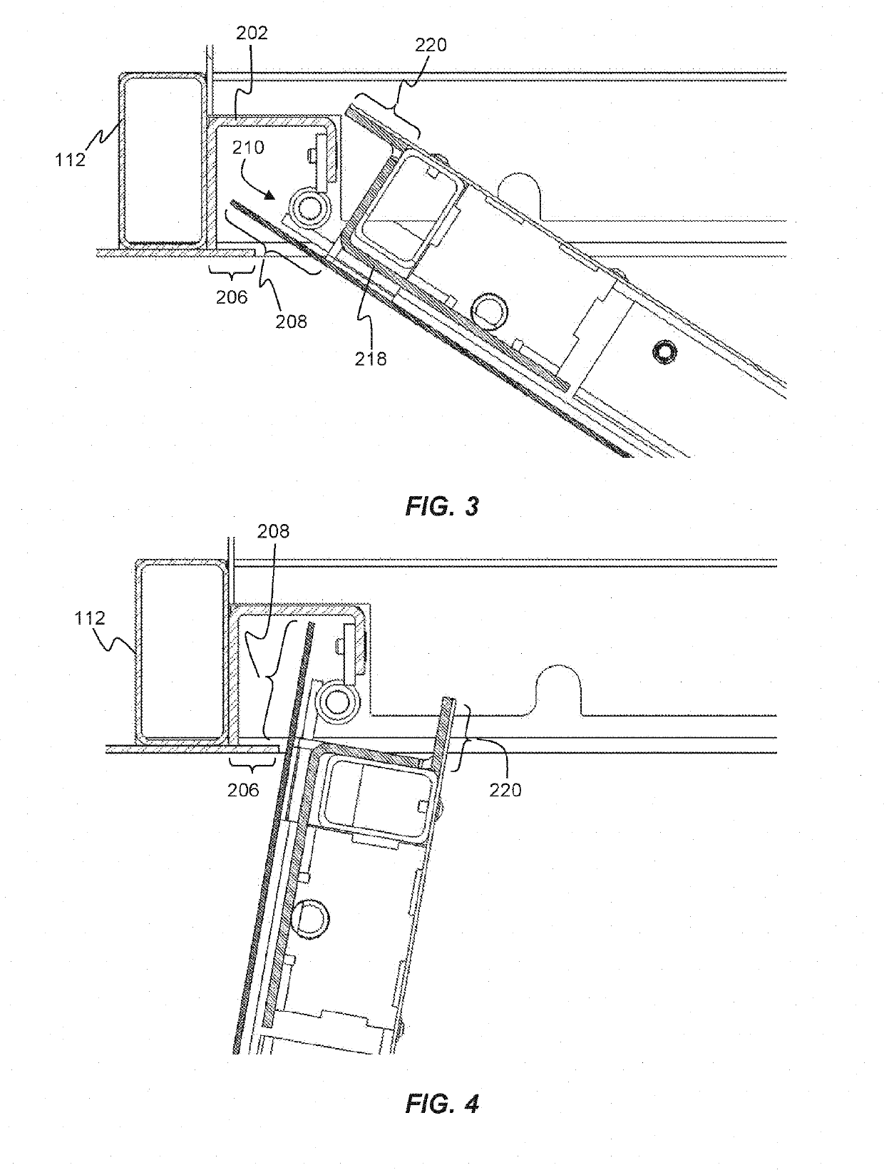
A security door hinge assembly is provided, comprising a door frame structure, having at least a head member, a first jamb member and a second jamb member, and at least one door leaf. The door leaf further comprises a leaf frame structure, having at least a top rail member, a bottom rail member, a hinge stile member and a lock stile member; an inner leaf panel, mounted to a first side of said leaf frame structure and extending past said hinge stile member, so as to form an inner leaf flange; an outer leaf panel, mounted to a second side of said leaf frame structure, opposite said first side, and extending past said hinge stile member, so as to form an outer leaf flange, and wherein, in use, said door leaf is operable between a first closed position and a second open position. The security door hinge assembly further comprises a hinge chamber positioned between said first jamb member and said hinge stile; a hinge-mount bracket, coupled to said first jamb member; a hinge mechanism, having at least one pivot axis and which is located within said open hinge chamber and adapted to pivotally mount said door leaf to said hinge-mount bracket, and wherein, in said first closed position, said inner leaf flange is in an exteriorly overlapping engagement with at least a portion of said hinge mount bracket, so as to prevent access to said hinge mechanism.

Description

[0001]The present invention relates to security doors and in particular to security door hinges. Even more particular, the present invention relates to a security door hinge assembly having hinges that are concealed and inaccessible when the security door is closed and during operation of the security door.INTRODUCTION[0002]Estate security is expensive to implement and maintain across a large regional or national geographic area, often because the dynamics of the threat can be locally influenced.[0003]Threats are dynamic, thus frequently making existing security systems redundant before the capital expenditure has been amortized. Consequently, sites at heightened risk remain exposed for longer then necessary due to the natural reluctance to discard existing costly security equipment and replace it, so as to allow protection against the new threat.[0004]Furthermore, nowadays, any type of information is instantly accessible via Internet based search engines and anybody can make themse...

Claims


Application Information

Patent Timeline
IPC IPC(8): E05D11/00E05D5/02E06B3/82E06B5/11
CPCE05D11/0027E05D5/0215E06B3/822E06B5/113E05D2011/0036E05Y2600/41E05Y2900/132E05D11/0018E05D7/14
Inventor TODD, ROBERT EDMUND
Owner HODGSON SAYERS LTD
Learn More