Liquid ejecting apparatus

a technology of liquid ejecting apparatus and ejector, which is applied in the direction of printing, other printing apparatus, etc., can solve the problem of large apparatus main body, and achieve the effect of preventing the main body of the apparatus from being larg

Active Publication Date: 2019-06-27
SEIKO EPSON CORP
View PDF0 Cites 3 Cited by
  • Summary
  • Abstract
  • Description
  • Claims
  • Application Information

AI Technical Summary

Benefits of technology

The invention provides a liquid ejecting apparatus that can prevent the main body from being too large. This is achieved by placing the liquid containing portion in the external region of the housing, so that it protrudes outward from the housing. Connecting the liquid replenishment member to the liquid containing portion can be facilitated by aligning the liquid supply portion of the replenishment member with the pouring port of the liquid containing portion, and using a guide portion. Additionally, a key slot is provided to determine the position of the pouring port, and a cover member is pivotably supported by the key slot to easily block the pouring port. The invention also includes a mounting member with a clearance adjustable to the position of the blocking member, to ensure the proper functioning of the apparatus.

Problems solved by technology

Therefore, in order to pour ink into an ink tank, it is necessary that the image reading device pivots to be located at an opened position and then the cover member is located at the opened position, which is troublesome.
In this regard, in order to enable the cover member to be located at the opened position without being locating the image reading device at the opened position, it is considered that the entire liquid containing portion is located in an external region of the apparatus main body which is located outside the front surface or the side surface forming an outline of the apparatus main body; however, in this case, there is a problem that the apparatus main body becomes large.

Method used


Image

  • Liquid ejecting apparatus
  • Liquid ejecting apparatus
  • Liquid ejecting apparatus

Examples


Embodiment Construction

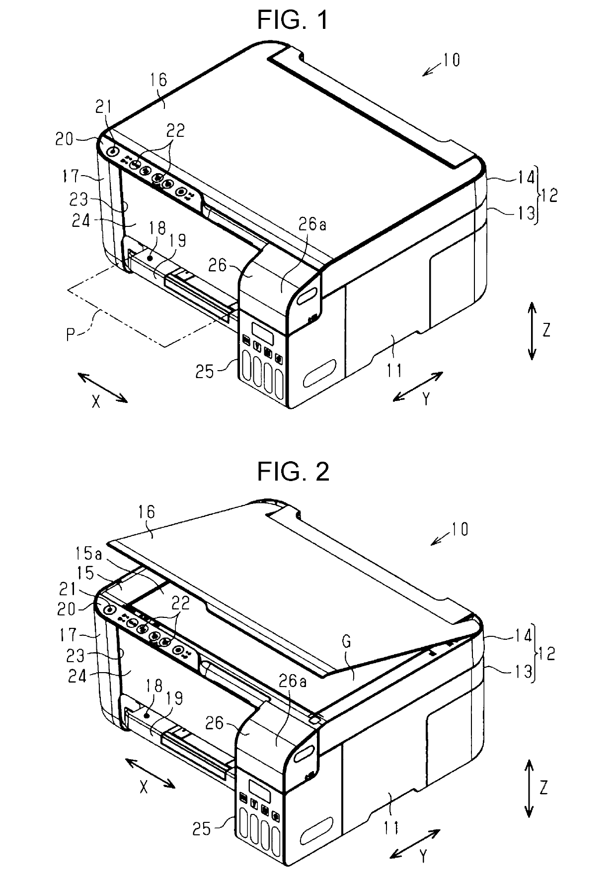
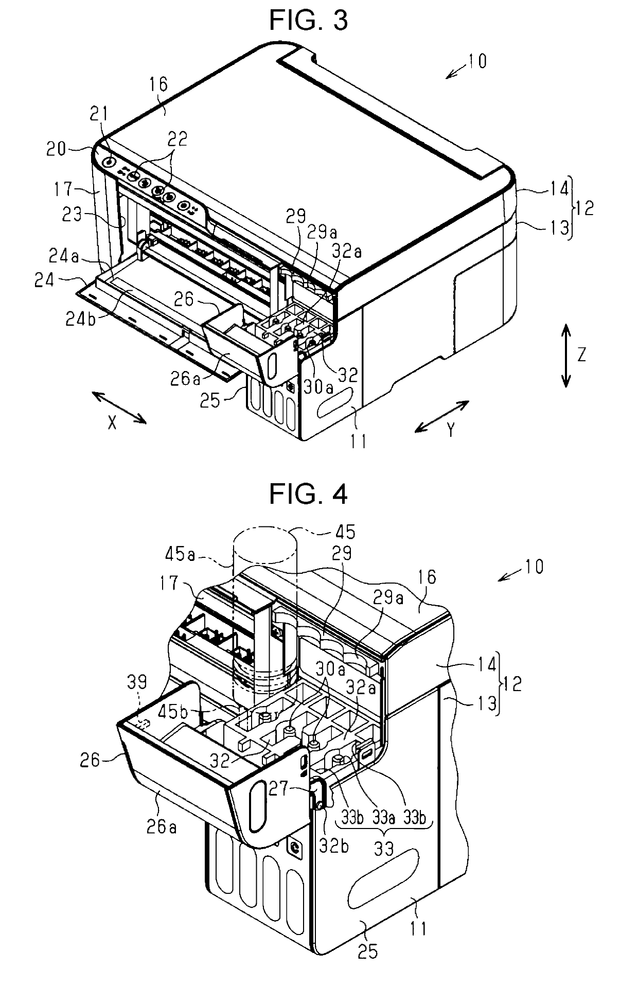
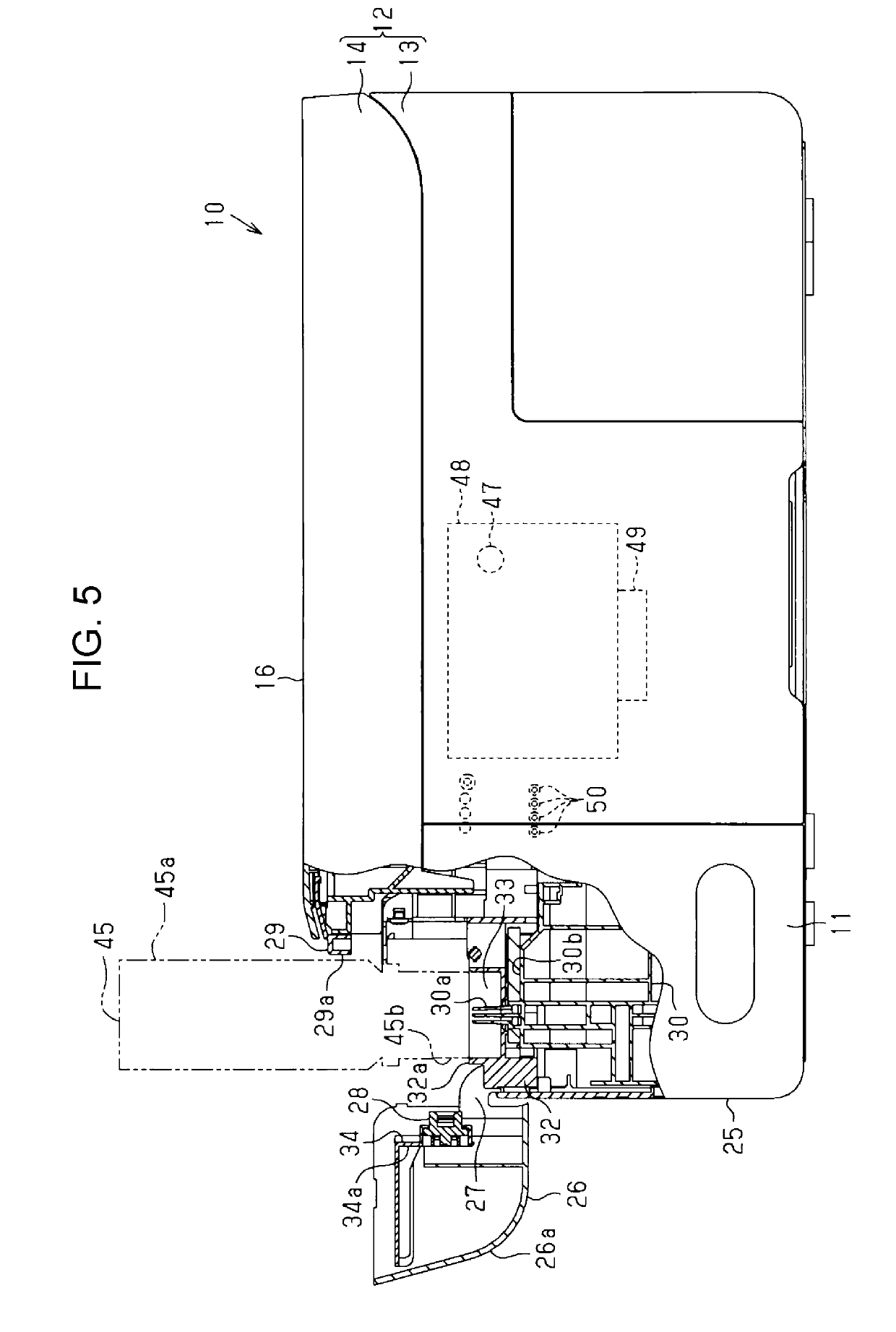
[0030]One embodiment of a liquid ejecting apparatus will be described below with reference to the drawings.

[0031]As illustrated in FIG. 1, a liquid ejecting apparatus 10 of the embodiment is an ink jet type printer that performs recording by ejecting ink, which is an example of a liquid, on a medium P such as a sheet, and is provided with a substantially rectangular parallelepiped apparatus main body 12 having a predetermined length as a height, a depth, and a width, respectively in a state of being installed in a horizontal use place. In FIG. 1, assuming that the liquid ejecting apparatus 10 is placed on a horizontal plane, a vertical direction is indicated by a Z axis, and a direction along the horizontal plane perpendicular to the vertical direction is indicated by an X axis and a Y axis. In the following description, the direction along the X axis is also referred to as a width direction, the direction along the Y axis is also referred to as a depth direction, and the width dire...


PUM


Abstract

In a liquid ejecting apparatus, a cover member, which is provided so that a part thereof is located in an external region of a housing and is displaceable between a closed position where a pouring port pouring a liquid is not exposed and an opened position where the pouring port is exposed, is at a position different from a position where the cover member overlaps an apparatus main body in a case where the apparatus main body is viewed from an upper surface of an image reading device at the opened position, and a liquid containing portion is provided at a position where at least a part of a liquid replenishment member connected to the pouring port overlaps the image reading device in a case where the apparatus main body is viewed from the side surface when the cover member is located at the opened position.

Description

BACKGROUND1. Technical Field[0001]The present invention relates to a liquid ejecting apparatus such as a printer.2. Related Art[0002]An ink jet type printer (liquid ejecting apparatus) including a liquid ejecting unit that ejects ink, which is an example of a liquid, to a sheet as an example of a medium has been known from the past. Some of such printers include an ink tank (liquid containing body) that contains ink to be supplied to the liquid ejecting unit contained in an apparatus main body. The ink tank is provided with a blocking member for blocking a pouring port in order to prevent the ink contained in the ink tank from leaking from the pouring port. For example, JP-A-2017-42995 discloses a printer in which a blocking member that blocks a pouring port of an ink tank is attached to a cover member that can open and close a liquid containing portion that contains the ink tank.[0003]In a printer disclosed in JP-A-2017-42995, an upper portion of an apparatus main body is configure...

Claims


Application Information

Patent Timeline
IPC IPC(8): B41J29/13B41J2/175
CPCB41J29/13B41J2/17506B41J2/21B41J2/17553B41J2/1752B41J2/17509B41J2/17523B41J29/02
Inventor OKAZAWA, YOSHIYUKITAKEUCHI, ATSUHIKO
Owner SEIKO EPSON CORP
Why Eureka
Try Eureka