Method and apparatus for automatically adjusting luminance of vehicle tail light

a technology of automatic adjustment and tail light, which is applied in the direction of control devices, external condition input parameters, vehicle components, etc., and can solve problems such as rear-end collisions

Active Publication Date: 2019-06-27
PARK GYEONGJUNE
View PDF12 Cites 11 Cited by
  • Summary
  • Abstract
  • Description
  • Claims
  • Application Information

AI Technical Summary

Benefits of technology

[0016]According to the present invention, it is advantageous in that when a distance between a vehicle and a following vehicle is within a preset section and the speed of the following vehicle is higher than the speed of the vehicle while the engine of the vehicle is ON, luminance of the tail lights on the rear side of the vehicle gradually or rapidly increases up to a predetermined brightness in response to a change in the difference of speed as the difference of speed between the vehicle and the following vehicle increases, and luminance of the tail lights on the rear side of the vehicle gradually or rapidly decreases to a normal brightness in response to a change in the difference of speed as the speed of the following vehicle becomes equal to the speed of the vehicle, and thus as the driver or passengers on the following vehicle recognize a change in the distance corresponding to a state of speed reduction of the vehicle and the change in the difference of speed through a change in the luminance of the tail lights on the rear side of the vehicle, a caution or a warning is given to the driver or passengers on the following vehicle when the following vehicle approaches the vehicle at a high speed so that a safe distance for preparing for an unexpected situation may be secured to prevent in advance a rear-end collision or a collision accident unforeseen.
[0017]In addition, a caution or a warning may be given as the luminance of the tail lights on the rear side of the vehicle changes even when the brake lamps are not lit due to abrupt natural reduction in the speed of the vehicle or when the vehicle stops as an emergency situation occurs, and there is an effect of double warning through the change in the luminance of the tail lights on the rear side of the vehicle even when the brake lamps are lit as the vehicle stops.
[0018]Moreover, according to another embodiment of the present invention, as the range of the maximum brightness value of the luminance of the tail lights on the rear side of the vehicle is automatically adjusted according to the speed of the vehicle, a stronger warning is given to the following vehicle when the vehicle runs at a high speed, and as a caution of advising to pay attention to the distance, rather than a warning, is given at a low speed, the present invention has effects different at a high speed and at a low speed.

Problems solved by technology

However, the rear combination lamp is disadvantage in that it does not have a function of giving a special caution or warning when the driver of the following vehicle approaches the vehicle within a safe distance at a speed higher than that of the vehicle without reducing the speed in response to braking of the vehicle, abrupt natural reduction in speed, stopping of the vehicle in an emergency case, or the like, and when the following vehicle approaches too close, it may cause a rear-end collision as the late braking of the following vehicle cannot prepare for an unexpected situation or the like.

Method used


Image

  • Method and apparatus for automatically adjusting luminance of vehicle tail light
  • Method and apparatus for automatically adjusting luminance of vehicle tail light
  • Method and apparatus for automatically adjusting luminance of vehicle tail light

Examples


Embodiment Construction

[0038]The features and advantages of the present invention will become more apparent from the following detailed description based on the accompanying drawings. Prior to this, the terms or words used in this specification and claims should be interpreted as meanings and concepts meeting the technical ideas of the present invention based on the principles that can define adequately the concept of the terms so that the inventor may explain his or her invention in the best way.

[0039]Hereinafter, a method and an apparatus for automatically adjusting luminance of a tail light on the rear side of a vehicle according to another preferred embodiment of the present invention will be described with reference to the accompanying drawings.

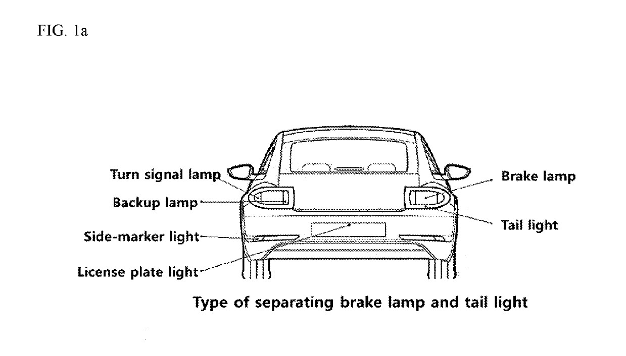
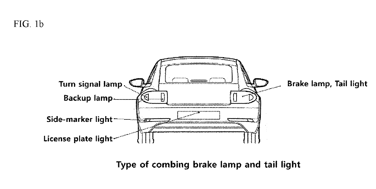
[0040]FIGS. 1a and 1b are views showing application parts of a rear combination lamp applied to a vehicle according to an embodiment of the present invention.

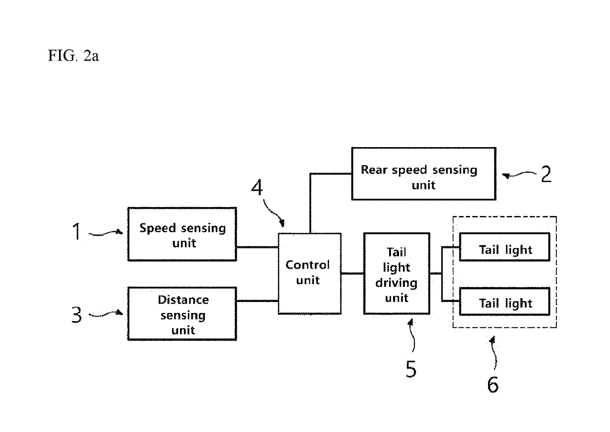
[0041]FIG. 2b is a block diagram showing a method of automatically adjusting luminance of a tail light...


PUM


Abstract

The present invention provides a method and an apparatus for dynamically controlling the luminance of a tail light of a vehicle tail lamp in response to a change in the difference of speed between a vehicle and a vehicle therebehind, and for preventing a collision between the traveling vehicles. In addition, the apparatus comprises: a tail light operating unit, which slowly or rapidly becomes brighter up to a predetermined brightness as the speed difference between the vehicle and the vehicle behind gradually becomes larger, and slowly or rapidly becomes darker down to a predetermined brightness as the speed difference between the vehicle and the vehicle behind gradually becomes smaller; a speed sensing unit for measuring the speed of the vehicle; a rear speed sensing unit for measuring the speed of the vehicle therebehind; and a control unit for automatically adjusting the luminance of the tail light by controlling the tail light operating unit when the vehicle therebehind is traveling faster than the vehicle.

Description

TECHNICAL FIELD[0001]The present invention relates to a method and an apparatus for preventing collisions between traveling vehicles, and more specifically, to a method and an apparatus for preventing collisions between vehicles, which dynamically control luminance of tail lights of vehicle tail lamps in response to a speed difference between a vehicle and a following vehicle.BACKGROUND[0002]Various types of lamps lit for safe driving are installed in a vehicle, and there are turn signal lamps, brake lamps, backup lamps, tail lights, emergency lights and the like on the rear side of the vehicle. The turn signal lamps perform a function of informing other vehicles or pedestrians of left and right traveling directions of the vehicle, which are mainly yellow color and flicker at regular intervals of one or two times a second. The brake lamps are red color and inform following vehicles that the vehicle is stopping when the driver stops the vehicle by stepping on the brake pedal. The bac...

Claims


Application Information

Patent Timeline
Patent Type & Authority Applications(United States)
IPC IPC(8): B60Q1/30B60W40/105B60Q9/00
CPCB60Q1/30B60W40/105B60Q9/008B60W2550/308B60W2420/60B60W2420/54B60W2420/40B60Q1/535B60Q1/00B60W2554/801
Inventor PARK, GYEONGJUNE
Owner PARK GYEONGJUNE
Why Eureka
Try Eureka