

Packing member for liquid container
- Summary
- Abstract
- Description
- Claims
- Application Information
AI Technical Summary
Benefits of technology
Problems solved by technology
Method used
Image

Examples
first embodiment
Summary of First Embodiment
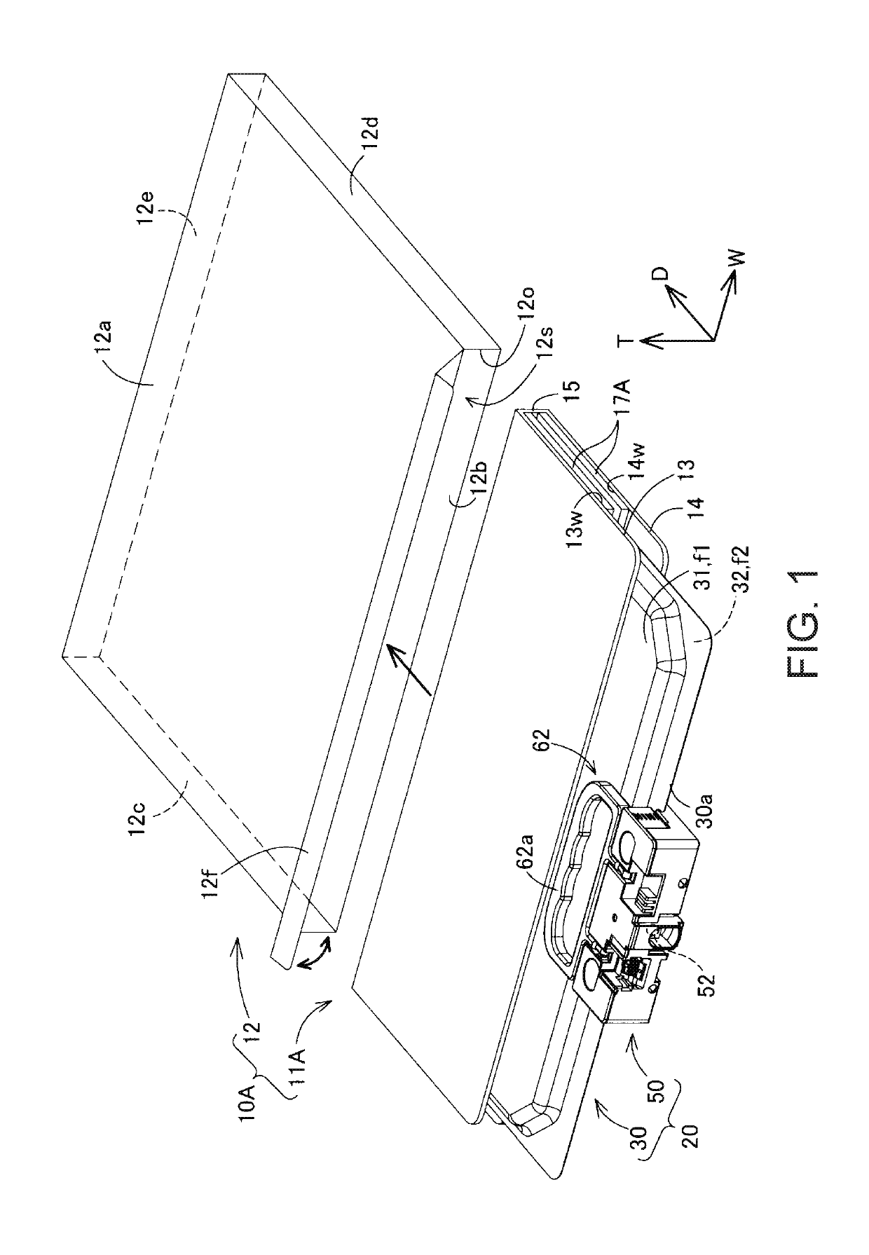
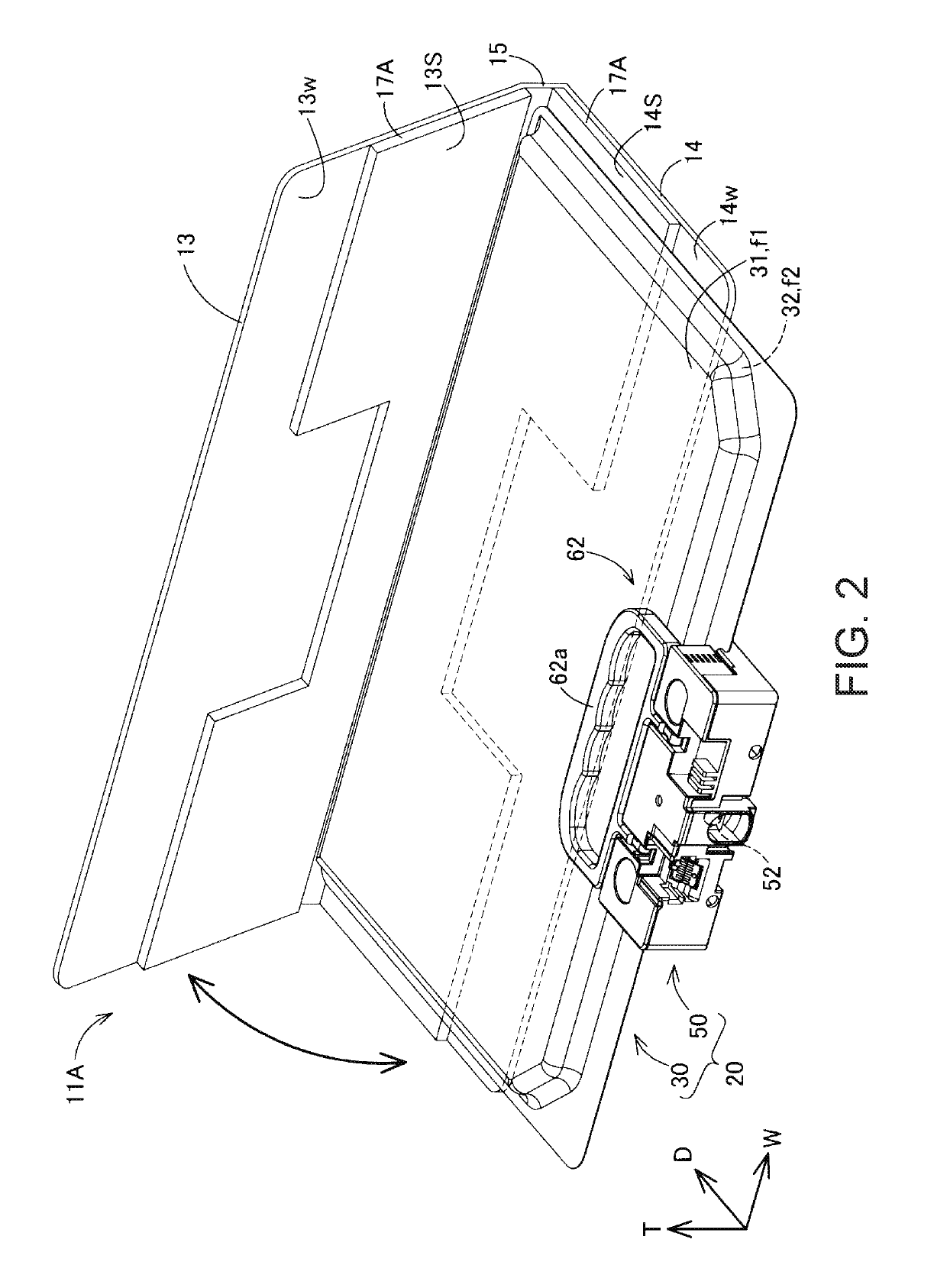
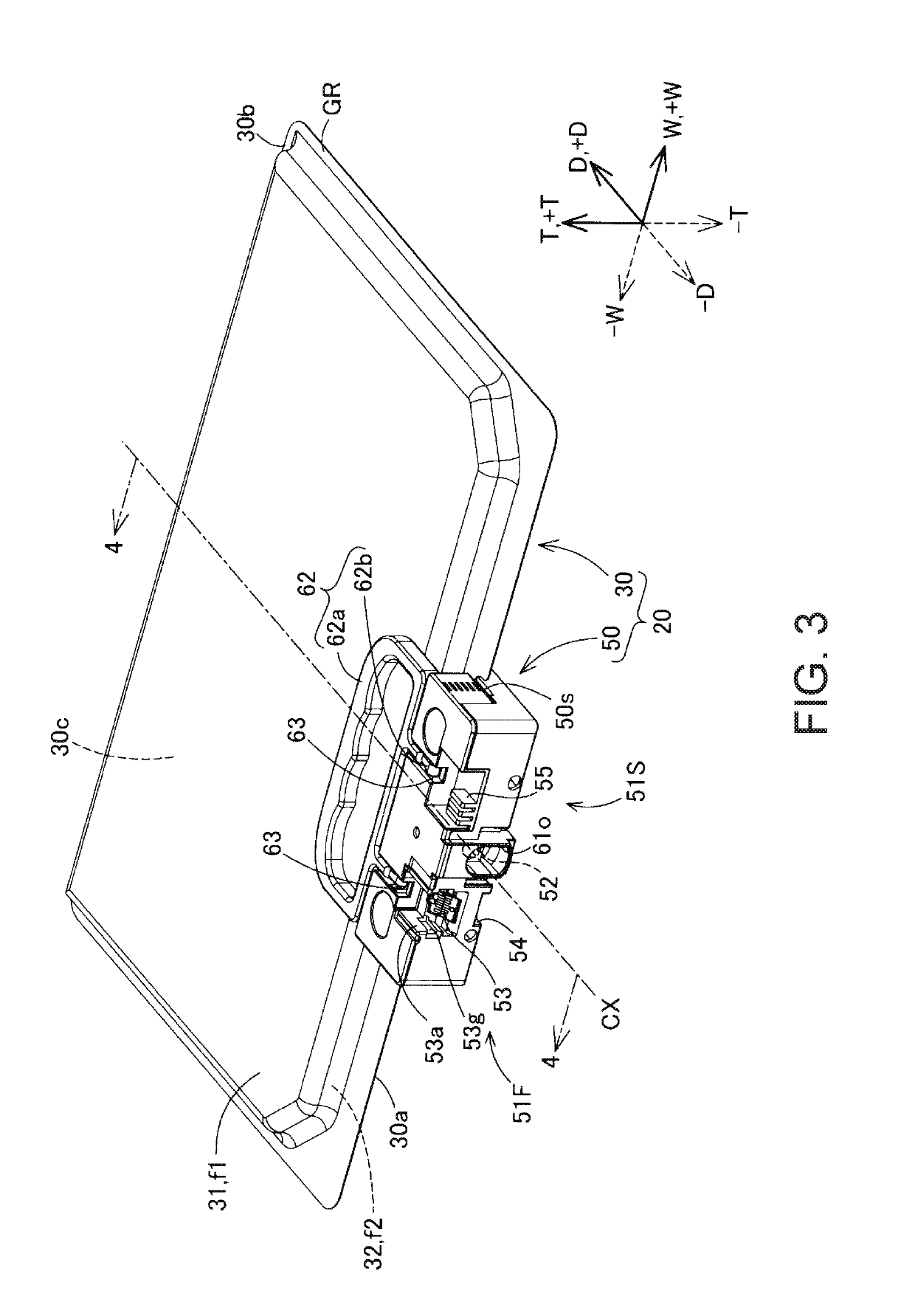
[0122]As described above, according to the packing member 10A of the first embodiment, the liquid container 20 is packed in a state where the pressure in the bag 30 is increased by the pressurizing portion 17A of the holding member 11A, and thus rippling of liquid in the bag 30 is suppressed. Therefore, in the liquid container 20 that is packed, deterioration of the bag 30 due to rippling of liquid, and deterioration of the liquid outlet member 65 contained in the bag 30 are suppressed. In addition, according to the package 100A of the first embodiment, for example, even if a load is imposed during transportation, conveyance, or the like, damage and deterioration of the liquid container 20 that is contained in the package 100A is suppressed as described above, and thus high durability against such a load is realized.
[0123]In addition, in the packing member 10A of the first embodiment, the first section 13 and the second section 14 of the holding member 11A...
second embodiment
2. Second Embodiment
[0124]FIG. 9 is a schematic plan view showing the configuration of a pressurizing portion 17B provided in a holding member 11B of a packing member 10B in a second embodiment. FIG. 9 illustrates the holding member 11B of the second embodiment and a liquid container 20 when developed from a fixed state. In FIG. 9, a region in which the pressurizing portion 17B is formed is hatched. Note that, in FIG. 9, for convenience, the adapter 50 is not illustrated. In addition, the liquid outlet member 65 is illustrated to be visible through the bag 30 such that the position at which the liquid outlet member 65 is arranged can be perceived.
[0125]The packing member 10B of the second embodiment is substantially the same as the configuration of the packing member 10A of the first embodiment, except that the holding member 11B of the second embodiment is provided in place of the holding member 11A of the first embodiment, and the packing member 10B is used for packing the same li...
third embodiment
3. Third Embodiment
[0128]FIG. 10 is a schematic plan view showing the configuration of a pressurizing portion 17C provided in a holding member 110 of a packing member 100 in a third embodiment. FIG. 10 illustrates the holding member 11C of the third embodiment and a liquid container 20 when developed from a fixed state. In FIG. 10, a region in which the pressurizing portion 17C is formed is hatched. Note that, in FIG. 10, for convenience, an adapter 50 is not illustrated. In addition, a liquid outlet member 65 is illustrated to be visible through a bag 30 such that the position at which the liquid outlet member 65 is arranged can be perceived.
[0129]The configuration of the packing member 100 of the third embodiment is substantially the same as the configuration of the packing member 10A of the first embodiment, except that the holding member 110 of the third embodiment is provided in place of the holding member 11A of the first embodiment, and the packing member 100 is used for pack...
PUM
 Abstract
Description
Claims
Application Information