Method and apparatus for joining a joining element onto a workpiece

Inactive Publication Date: 2019-07-11
NEWFREY
View PDF0 Cites 0 Cited by
  • Summary
  • Abstract
  • Description
  • Claims
  • Application Information

AI Technical Summary

Benefits of technology

The patent describes a cleaning process for joining materials together using a joining device. The cleaning process is preferably performed while a joining element is already in place on the workpiece. This is beneficial for ensuring optimal cleaning results. The detection device used for this process can also use an active component to measure physical quantities on the workpiece. This provides flexibility in the detection device's capabilities. Overall, this patent aims to improve the efficiency and precision of the joining process.

Problems solved by technology

In particular, these problems are present when the workpiece and the joining element are respectively made of an aluminium alloy.
In addition, problems can arise in terms of uneven grain sizes on the upper layer, which layer can reach to a depth of up to 1 mm, to be precise in particular in the case of extrusion moulding material.
Such uneven grain sizes can lead to divergent conductivities.
This produces the problem that the surface is coated with release agents, which can be constituted by waxes, oils, polysiloxanes, hydrocarbons, polymers, etc.
In particular when the coating with such release agents is uneven across the area, it is difficult to suitably adapt joining parameters.
In the case of a coating with carbon, this can lead to pores or shrink holes in the welded joint, thus all in all to a higher porosity of the welded joint, which can adversely affect the strength of the welded joint.
Generally speaking, although materials having defined surface specifications are requested, practice shows that these surface specifications, to which a joining process is then specifically tailored in terms of the joining parameters, are not always properly observed.
A problem with this process is that such impurities can subsequently on the other joining surface attach themselves to the stud, so that, in this case too, problems can arise in terms of consistent joining connections.

Method used


Image

  • Method and apparatus for joining a joining element onto a workpiece
  • Method and apparatus for joining a joining element onto a workpiece

Examples


Embodiment Construction

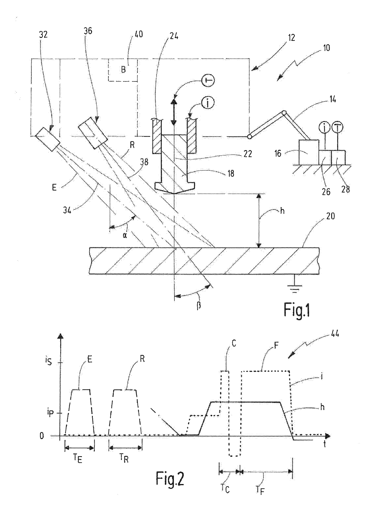
[0065]In FIG. 1 a joining apparatus is represented in schematic form and is denoted in general terms by 10.

[0066]The joining apparatus 10 comprises a joining head 12 or a joining gun, wherein the joining head 12 is preferably fixed to an arm 14 of a robot 16 and is hence movable in three dimensions in space.

[0067]The joining apparatus serves to join joining elements 18 onto workpieces 20. The joining elements can, in particular, be studs. The workpieces 20 can, in particular, be metal plates. The joining apparatus 10 is preferably used in the field of body making of motor vehicles.

[0068]The material of the workpiece 20 and of the joining element 18 is respectively preferably aluminium or an aluminium alloy.

[0069]For the performance of a joining process, the joining element 18 is held in a holding device 24 of the joining head 12 and oriented in a joining axis 22, which is preferably perpendicular to a surface of the workpiece 20.

[0070]The holding device 24 is preferably connected to...


PUM

PropertyMeasurementUnit
Timeaaaaaaaaaa
Timeaaaaaaaaaa
Angleaaaaaaaaaa

Abstract

A method for joining a joining element onto a workpiece, in particular for stud welding or stud gluing. The method steps including providing the joining element the workpiece; detecting a characteristic variable of the workpiece or of the joining element; evaluating the characteristic variable and classifying it into one a first or a second variable class; performing the joining process, if the characteristic variable is classified into the first variable class; or performing a cleaning process on the workpiece or on the joining element and then performing the joining process after the cleaning process, if the characteristic variable is classified into the second variable class.

Description

CROSS-REFERENCE TO RELATED APPLICATION[0001]This application is a continuation of international application PCT / EP2017 / 072253, filed Sep. 5, 2017 which claims priority from German Patent Application No. 102016117177.8 filed Sep. 13, 2016, the disclosures of which are incorporated herein by reference in their entirety.BACKGROUND OF THE INVENTION[0002]The present invention relates to a method for joining a joining element onto a workpiece, in particular for stud welding or stud gluing.[0003]The present invention further relates to a joining apparatus for joining a joining element onto a workpiece, in particular for implementing the above-stated method, wherein the joining apparatus has a joining head, which comprises a holding device for a joining element and by means of which the joining element is movable along a joining axis in relation to a workpiece.[0004]A joining method of this type and an associated joining apparatus are widely known, for instance in the field of so-called stu...

Claims


Application Information

Patent Timeline
IPC IPC(8): B23K9/20B23K9/095B23K9/235B23K11/00B23K11/34B23K11/36
CPCB23K9/20B23K9/095B23K9/235B23K11/004B23K11/34B23K11/36
Inventor EISSARA, BAHMESCHUT, GERSONREIS, CHRISTIAN
Owner NEWFREY
Why Eureka
Try Eureka