
Railway track maintenance trolley

a technology for maintenance trolleys and track tracks, applied in the direction of track maintenance, railway inspection trolleys, railway tracks, etc., can solve the problems of cumbersome operation without risk of operator injury, and the inability to power the workhead from an independent and external power sour

Active Publication Date: 2019-07-11
MELVELLE EQUIP CORP
View PDF10 Cites 3 Cited by
  • Summary
  • Abstract
  • Description
  • Claims
  • Application Information

AI Technical Summary

Benefits of technology

The present invention provides a railway track trolley that includes a pair of carriages that can slide relative to each other, a workhead that can be moved along the railway track, and a coupling assembly that connects the carriages for sliding movement. The trolley is powered and the workhead is mounted on a boom assembly that includes biasing means to support its weight. The technical effects of the invention include improved efficiency and flexibility in performing work at railway tracks, as well as improved safety and reliability due to the use of hydraulic power and a closed-circuit system for power takeoff.

Problems solved by technology

Although this clip remover is a significant advance on competing designs, it nonetheless has the following drawbacks:1. the single workhead must be moved across its trolley in order to access fasteners on the opposing track and this may be cumbersome to achieve without a risk of operator injury;2. if the trolley is modified to accommodate two (2) workheads they cannot always be operated simultaneously as sleepers are not generally square to the associated track and thus opposing fasteners not aligned with the respective workheads;3. the workhead is counterbalanced with the power source which means the workhead cannot be powered from an independent and external power source.

Method used


Image

  • Railway track maintenance trolley
  • Railway track maintenance trolley
  • Railway track maintenance trolley

Examples


Embodiment Construction

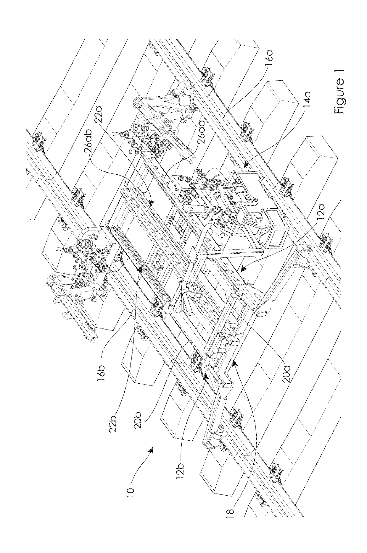
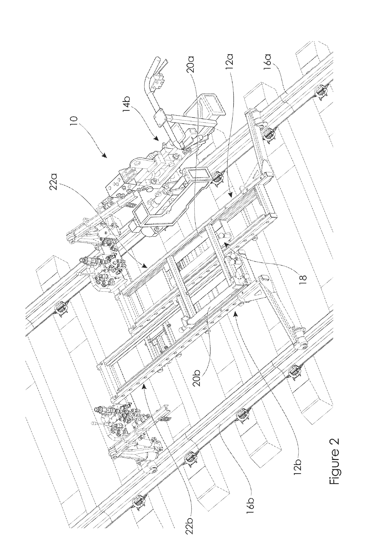
[0030]As shown in FIGS. 1 and 2 there is a railway track trolley 10 according to an embodiment of a first aspect of the invention. The railway track trolley 10 generally comprises a pair of carriages 12a and 12b, and a workhead such as 14a mounted to at least one of the pair of carriages such as 12a. The carriage 12a is adapted to locate on one of a pair of railway tracks 16a whereas the other carriage 12b locates on the other railway track 16b. The carriages 12a / b are interconnected via a coupling assembly 18 to permit independent sliding of the carriages 12a / b relative to one another. In operation, at least one of the carriages such as 12a is moved along the corresponding railway track 16a wherein its associated workhead 14a is adapted to implement work at that railway track 16a.

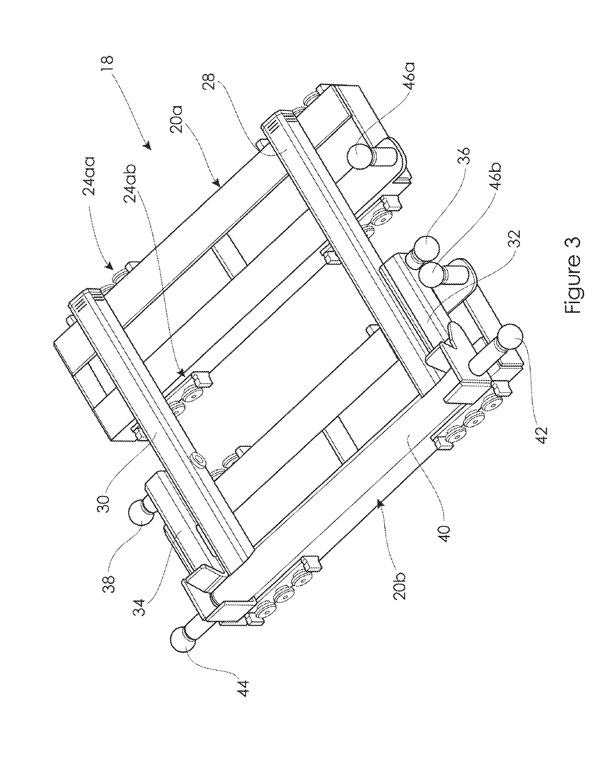
[0031]As best seen in FIGS. 3 to 5, the coupling assembly 18 of this embodiment is slidably mounted to, and located between, the pair of carriages 12a / b. The coupling assembly 18 includes a pair of cars 2...


PUM


Abstract

A railway track trolley includes a pair of carriages and a workhead mounted to at least one of the pair of carriages. The carriage is adapted to locate on one of a pair of railway track whereas the other carriage locates on the other railway track. The carriages are interconnected via a coupling assembly to permit independent sliding of the carriages relative to one another. In operation, at least one of the carriages is moved along the corresponding railway track wherein its associated workhead is adapted to implement work at that railway track.

Description

TECHNICAL FIELD[0001]The present invention relates broadly to a railway track trolley and relates particularly, although not exclusively, to a railway track maintenance or construction trolley.BACKGROUND OF INVENTION[0002]Maintenance trolleys are used in the rail industry to assist with both ongoing and periodic maintenance of the railway track and associated components such as rail clip fasteners. The trolley is typically arranged for rolling along an opposing pair of tracks, and a workhead mounted to the trolley is operated by a maintenance operator. In one application the workhead is designed for the insertion and / or removal of rail clip fasteners. The applicant has a unique rail clip remover which is the subject of patent protection in Australia and elsewhere, see PCT publication No. W02012 / 083339. Although this clip remover is a significant advance on competing designs, it nonetheless has the following drawbacks:[0003]1. the single workhead must be moved across its trolley in o...

Claims


Application Information

Patent Timeline
Patent Type & Authority Applications(United States)
IPC IPC(8): E01B29/24E01B31/02E01B29/32
CPCE01B29/24E01B31/02E01B29/32B61D15/12B60L2200/26E01B2203/01B61D15/08E01B31/00
Inventor MELVELLE, ANDREWDE ROOY, BENMORRIS, GARYCASBOULT, JASON
Owner MELVELLE EQUIP CORP
Learn More