
Anomaly Detection in Software Defined Networking

a software defined networking and anomaly detection technology, applied in the field of communication, can solve problems such as new security challenges, and the challenge of applying these mechanisms to new elements such as software defined networking (sdn) and network function virtualization (nfv)

Active Publication Date: 2019-07-11
NOKIA SOLUTIONS & NETWORKS OY
View PDF0 Cites 9 Cited by
  • Summary
  • Abstract
  • Description
  • Claims
  • Application Information

AI Technical Summary

Benefits of technology

The patent describes a new invention and its technical effects. The subject matter of the patent is set out in the independent claims, while the details of the implementation are outlined in the accompanying drawings and description. The technical effects of this invention are not described specifically in the text, but other features can be inferred from the description and accompanying drawings.

Problems solved by technology

New network technologies such as cloud computing bring new security challenges.
However, applying these mechanisms to new elements such as software defined networking (SDN) and network functions virtualization (NFV) is a challenge.

Method used


Image

  • Anomaly Detection in Software Defined Networking
  • Anomaly Detection in Software Defined Networking
  • Anomaly Detection in Software Defined Networking

Examples


first embodiment

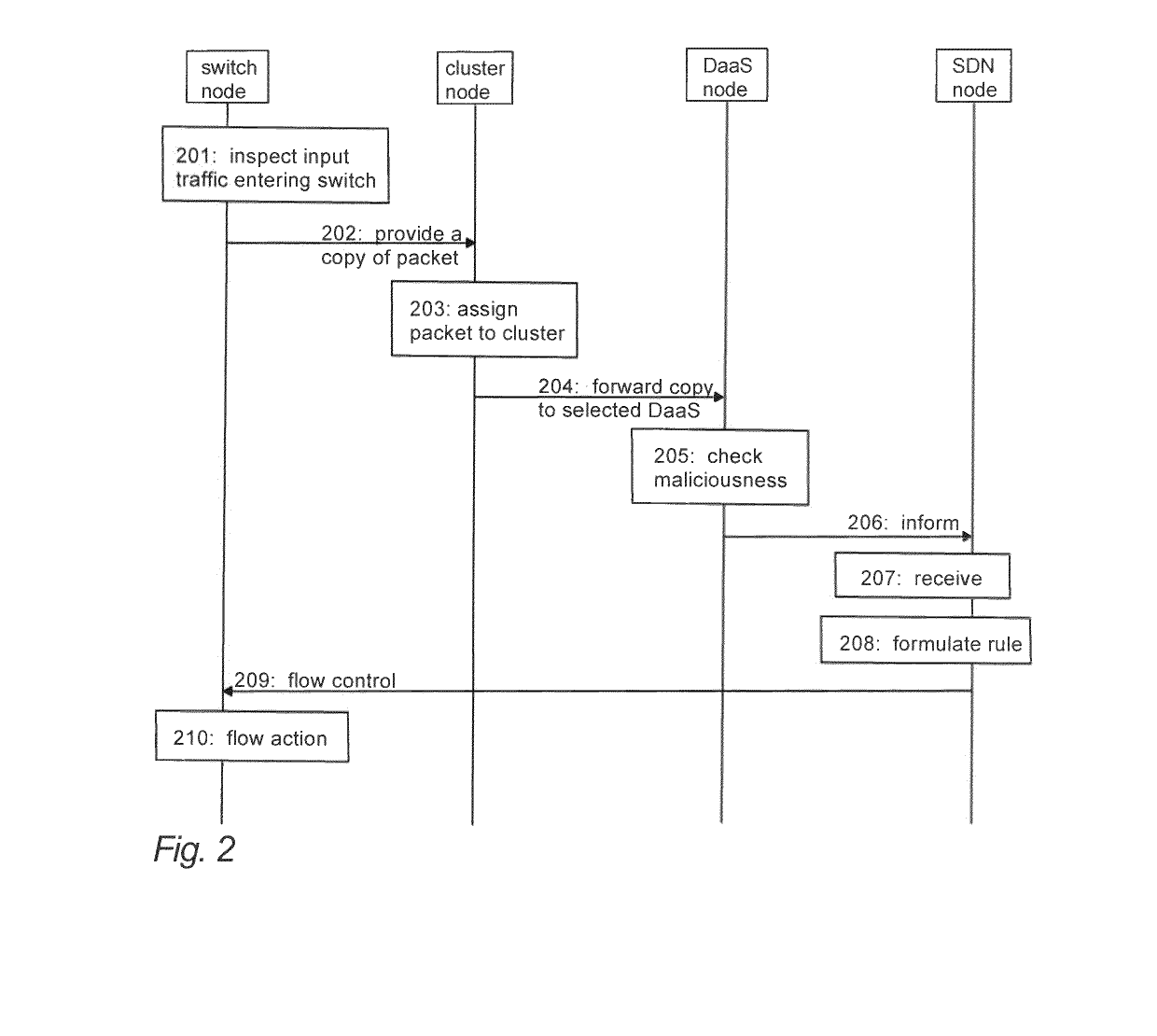
[0030]Referring to FIG. 2, in a first embodiment, input traffic entering a switch node is inspected (block 201) in the switch node. During the inspection, a forwarding table of the switch node may be checked in order to decide whether to pass a traffic flow or drop the traffic flow. If the traffic flow is safe, the switch node provides (block 202) a copy of a packet contained in the traffic flow to a cluster node. The cluster node selects (block 203) at least one detector node (DaaS node) based on the features of said copy. Said copy is forwarded (block 204) from the cluster node to the selected DaaS node among one or more DaaS nodes. The DaaS node checks (block 205) whether the said copy is malicious or not. If said copy is malicious, the DaaS node indicates (block 206) the corresponding traffic flow to a control node. The control node may be an SDN node comprising an SDN controller and / or an SDN application (SDN orchestrator).

[0031]The SDN node receives (block 207) the decision on...

second embodiment

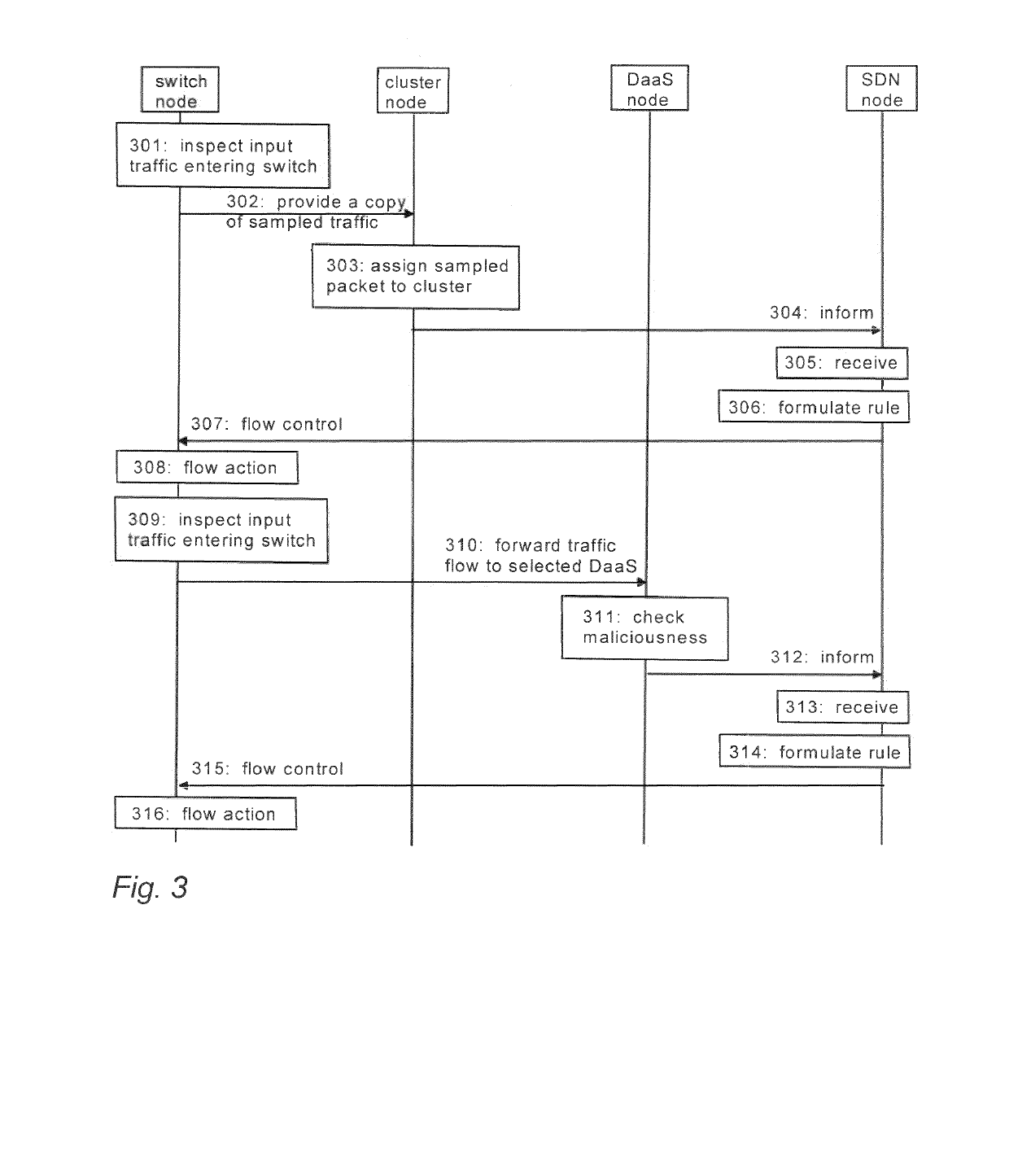
[0032]Referring to FIG. 3, in a second embodiment, clustering is carried out on a sampled packet instead of every packet. Input traffic is inspected (block 301) in the switch node. During the inspection, a forwarding table of the switch node may be checked in order to decide whether to pass the traffic flow or drop the traffic flow. If the traffic flow is safe, the switch node sends (block 302) a sample of the traffic flow (i.e. a sampled packet) to a cluster node according to a specified sampling rate. The cluster node defines (block 303) clusters based on the features of the sampled packet, and sends (block 304) cluster information and the sampled packet to a control node. The control node may be an SDN node comprising an SDN controller and / or an SDN application (SDN orchestrator). The SDN node receives (block 305) the cluster information and the sampled packet from the cluster node. The SDN node (SDN orchestrator) formulates (block 306) forwarding rule (so called flow in the Open...


PUM


Abstract

A network apparatus of a communication system classifies traffic flows containing packets based on packet features. The network apparatus provides a copy of a packet contained in a traffic flow to a cluster node, and controls the cluster node to select at least one detector node based on the features of the packet and to forward said copy to the selected detector node to find out based on said copy whether the packet is malicious or not. In response to receiving from the detector node a flow indication on the traffic flow, the network apparatus controls a switch node to perform at least one flow control action on the traffic flow, the action including one or more of flow removal, flow modification and flow installation

Description

TECHNICAL FIELD[0001]The invention relates to communications.BACKGROUND[0002]New network technologies such as cloud computing bring new security challenges. In a cloud computing infrastructure, security threats and their detection and prevention mechanisms are almost similar to those of conventional networks. However, applying these mechanisms to new elements such as software defined networking (SDN) and network functions virtualization (NFV) is a challenge. While different solutions such as security zones and grouping, isolating applications by virtual machines (VM) and licensing may be used for these elements, intrusion detection system (IDS) are still required in the network as a defence solution. IDS monitors network traffic in real time and compares received packet patterns with known patterns to detect anomalies in the network traffic.BRIEF DESCRIPTION[0003]According to an aspect, there is provided the subject matter of the independent claims. Embodiments are defined in the de...

Claims


Application Information

Patent Timeline
Patent Type & Authority Applications(United States)
IPC IPC(8): H04L29/06H04W12/12H04W28/10
CPCH04W28/10H04L63/0236H04L63/1425H04W12/1201H04L63/1416H04W12/122H04W12/121
Inventor MONSHIZADEH, MEHRNOOSHKHATRI, VIKRAMAJEETHATONEN, KIMMO KALERVOKALLIOLA, AAPO
Owner NOKIA SOLUTIONS & NETWORKS OY
Learn More