
Control of image capture

a technology of image capture and control, applied in the direction of instruments, measurement devices, using reradiation, etc., can solve the problem of somewhat controlled exposur

Active Publication Date: 2019-07-25
SONY SEMICON SOLUTIONS CORP
View PDF0 Cites 7 Cited by
  • Summary
  • Abstract
  • Description
  • Claims
  • Application Information

AI Technical Summary

Benefits of technology

The invention relates to a method and apparatus for controlling the exposure of a time-of-flight image capture sensor. The method involves detecting a portion of a tap value that is dependent on the integration period and selecting the next integration period so that the largest tap value is substantially equal to the difference between the required tap value and the portion that is independent of the integration period. This results in a higher accuracy of the captured image. The technical effect is an improvement in the accuracy of image capture using a time-of-flight sensor.

Problems solved by technology

Exposure control is a somewhat different issue in TOF sensors to “normal” image sensors producing an image such as a photograph to be viewed by a user.

Method used


Image

  • Control of image capture
  • Control of image capture
  • Control of image capture

Examples


Embodiment Construction

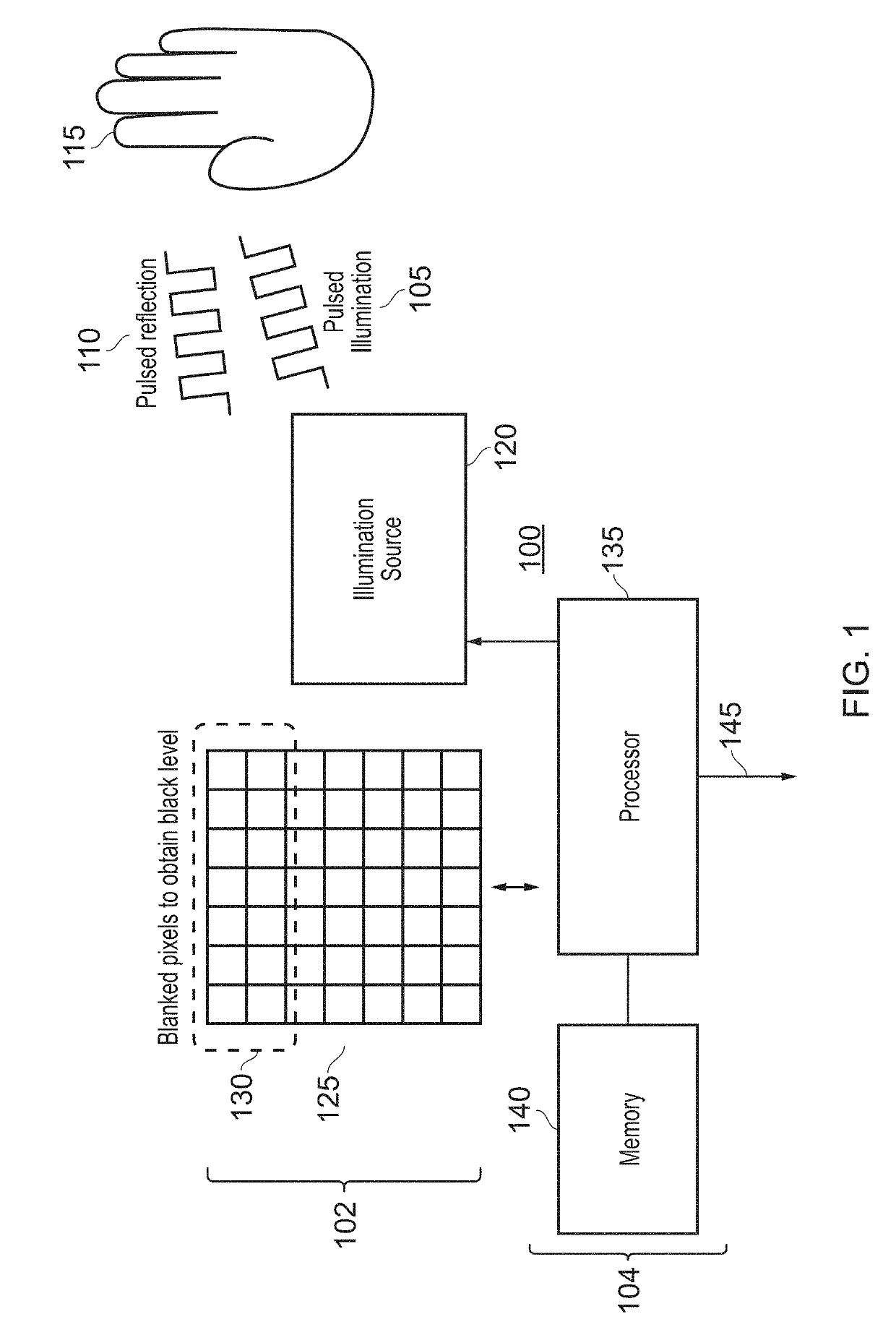
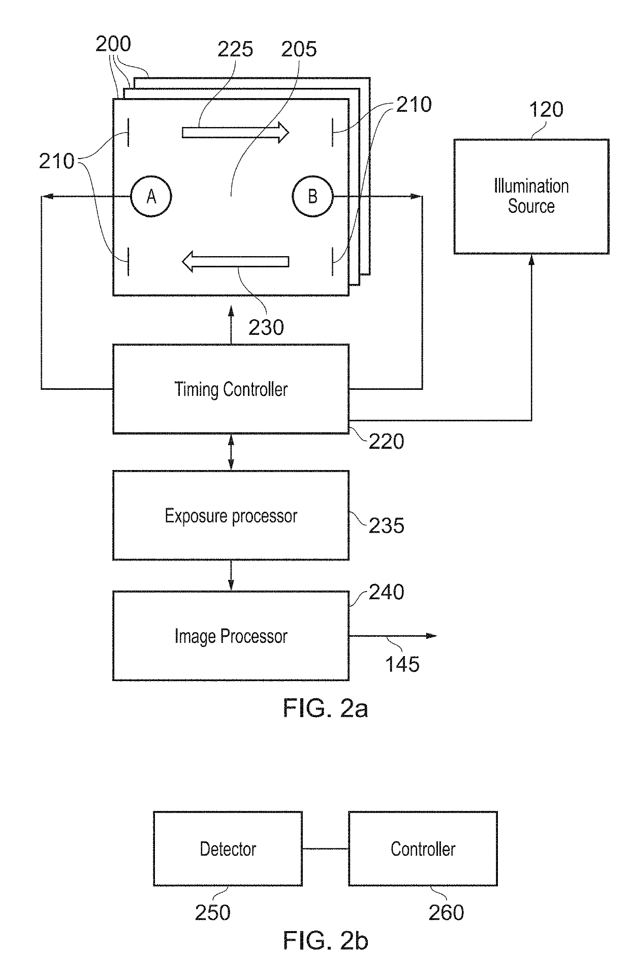
[0031]FIG. 1 schematically illustrates an image capture apparatus 100, and in particular a so-called time-of-flight (TOF) image capture sensor 102 and associated control electronics 104 acting as exposure control apparatus configured to control an integration period of the image capture sensor.

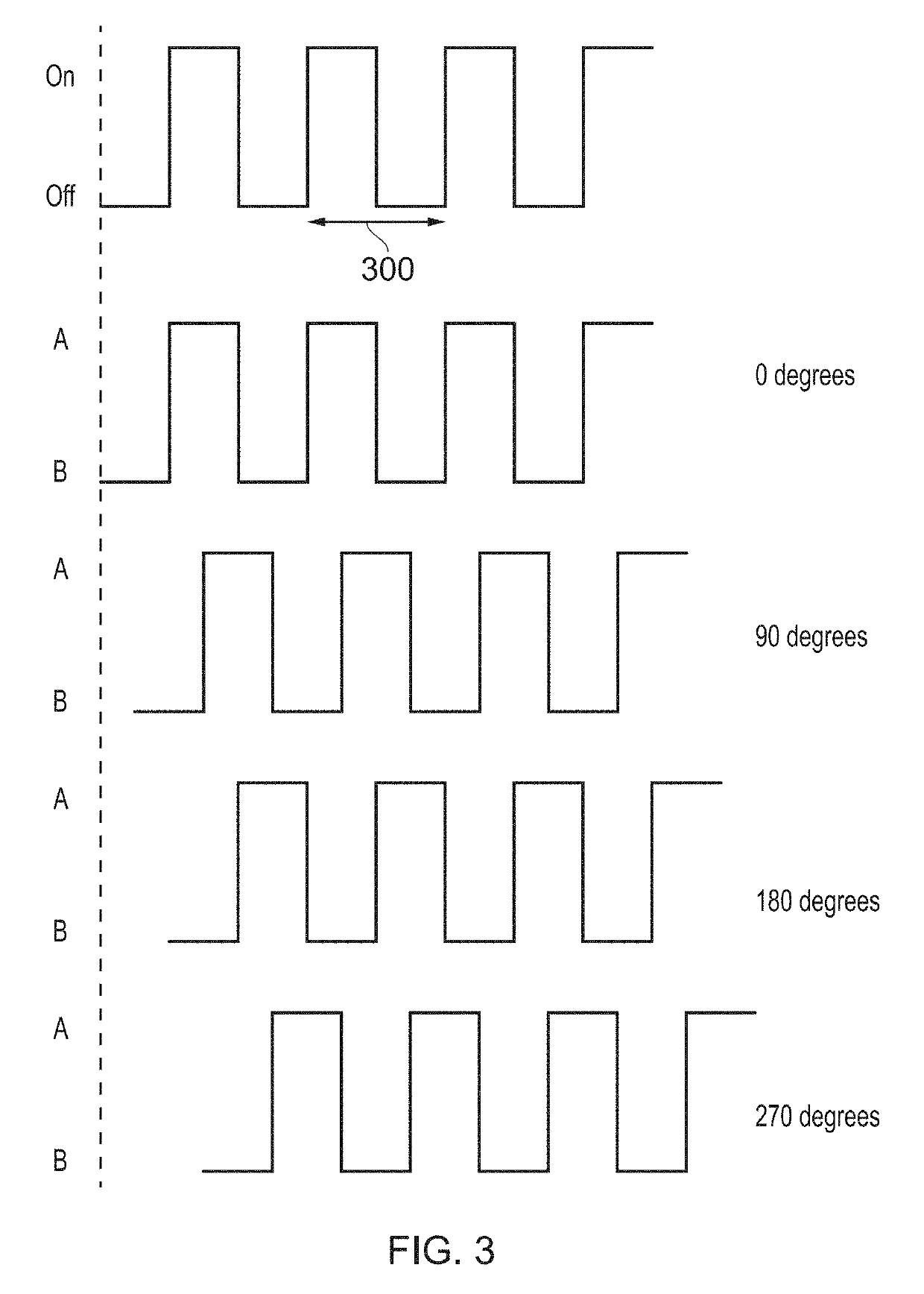
[0032]A TOF camera operates by providing pulsed or modulated illumination 105 and then detecting the reflected light 110 from a scene or object 115. A depth separation between the sensor and the object 115 can be detected by observing a phase shift between the illumination 105 and the reflection 110.

[0033]In FIG. 1, the illumination is provided by an illumination source 120 which provides the pulsed illumination 105 at a pulse repetition frequency of for example 40 MHz. An image is detected by an array 125 of pixel elements.

[0034]As discussed in more detail below, a subset 130 of one or more of the pixels (for example one or two lines of pixels in the array) is blanked from incident light. Thi...


PUM


Abstract

Exposure control apparatus to control an integration period of a time-of-flight image capture sensor comprising an illumination source providing pulsed illumination at a pulse repetition frequency, in which each pixel of an array of pixels is represented by multiple pairs of tap values, each pair of tap values being indicative of light sampled according to a pulsed sampling pattern having a respective phase relationship with the pulsed illumination of the illumination source comprises a detector configured to detect, for a selected tap value of a set of one or more target pixels, a portion of that tap value which is independent of the integration period and a portion which is dependent upon the integration period; and a controller configured to select a next integration period for the image capture sensor so that for a next pixel integration of the set of one or more target pixel values, the portion of the largest tap value which is dependent upon the increased integration period is substantially equal to the difference between the required tap value and the portion which is independent of integration period.

Description

CROSS REFERENCE TO RELATED APPLICATIONS[0001]The present application claims priority to European Patent Application serial number 14200467.0 filed in the European Patent Office on Dec. 29, 2014, the entire contents of which is incorporated herein by reference.BACKGROUNDField of the Disclosure[0002]This disclosure relates to the control of image capture.Description of the Prior Art[0003]The “background” description provided herein is for the purpose of generally presenting the context of the disclosure. Work of the presently named inventors, to the extent it is described in this background section, as well as aspects of the description which may not otherwise qualify as prior art at the time of filing, are neither expressly or impliedly admitted as prior art against the present disclosure.[0004]It is known to generate three-dimensional images using a so-called time-of-flight (TOF) image capture sensor comprising an illumination source providing pulsed illumination at a pulse repetiti...

Claims


Application Information

Patent Timeline
IPC IPC(8): G01S17/89G01S7/486G01S17/08G01S7/4863G01S7/4865
CPCG01S17/89G01S7/4865G01S17/08G01S7/4863
Inventor HITOMI, YASUNOBU
Owner SONY SEMICON SOLUTIONS CORP
Learn More